The Converter Racks A and B are
the first stage of processing beyond the antenna where the optical fibers
carrying the IF
signals from the receiver room on the GBT terminate at the Optical Receivers
in the Equipment Room in the Jansky Laboratory Building over 6 km from
the GBT.
The signals are demodulated from
optical to RF in the Optical Receivers then sent to the input switches
on the 1-8 GHz Converters by coaxial cables manually patched on the front
panels of the Converter Racks, the specific patching is shown in the IF
Manager screen. In the Converters the signal is
shifted by mixing the 1-8 GHz IF with a local oscillator signal designated
LO2 and provided to pairs of Converters by one of eight Gigatronics 605
synthesizers, then filtered to a 1.85 GHz bandwidth centered at 9.43 GHz.
LO2 is variable over a 10.5 to 18 GHz range providing tuning capability
over the entire 1-8 GHz range of the first IF, and components in the Optical
Receivers and 1-8 GHz converters are specified to operate from 100 MHz
to 8 GHz should the need arise to carry IF signals below 1 GHz. After
filtering at 9.43 GHz the signal is mixed with a 10.50 GHz signal designated
LO3 and converted down to a filtered 150-2000 MHz IF and switched to any
of four outputs: 1. The
1.6 GHz samplers, 2. A 500 to 1000 MHz band pass
filter in turn feeding the Very
Long Baseline Array Data Acquisition Recorder,
3. A spare output covering the full 150-2000 MHz bandwidth or 4.
To a 550 MHz low pass filter feeding a four way power divider in turn feeding:
1. The Spectral
Processor, 2. The 100
MHz Converter/Filters, and 3,4. Two spare outputs.
LO2 and LO3 are derived from a 10 MHz reference signal which in turn is
derived from the master hydrogen maser in the GB
Site Timing Center. The power level of the 150-2000
MHz IF is determined by coupling the signal to a square law detector.
That detected voltage is indicated on the Converter CLEO screens under
'CM Power (V)' and on a meter on the front panel of the 1-8 GHz Converter.
Each detector is measured to determine its individual voltage versus power
characteristics and the data from those measurements is available here.
Initial CLEO Converter Rack Screen:
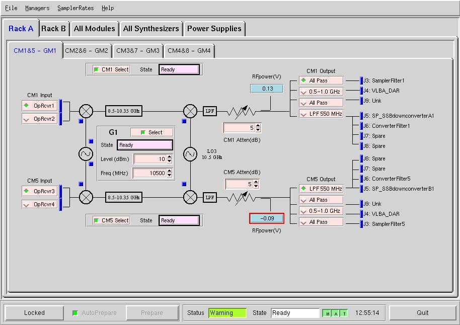
The top row of the initial CLEO Converter Rack screen has the Menu
Bar common to most CLEO screens. The next row
has five tabs to open a screen for Converter Rack A containing Converters
1-8 and LO2 Synthesizers 1-4, Rack B containing Converters 9-16 and LO2s
5-8, a screen of parameters for all sixteen Converter Modules, a screen
of parameters for all eight LO2 synthesizers and a tab showing voltages
for the rack power supplies. At the bottom of the screen is the State/Status
frame common to CLEO device and manager
screens.
The third row of the screen has four tabs, each allowing access to information
and parameters
for the Converters and their dedicated LO synthesizer. Adjustable
(after unLocking
the module) parameters include Input buttons for selecting the IF signal
from one of two optical receivers, parameters
in the path to enable the user to set attenuation levels from 1/8 to 31.875
dB in 1/8 dB steps, buttons for which of the four Outputs to be selected,
and buttons to place the Converters in or out of control of the Converter
Rack Manager
labeled 'CMx Select' in a frame with an indicator for the Converter control
status. Indicators for the IF3 RF power level after the Attenuator
show a voltage output from a detector for each Converter. This voltage
is exponentially proportional to the RF power level, a voltage of 0.1 volts
is approximately -40 dBm, 1 volt is approximately -30 dBm and 10 volts
approximately -20 dBm, better accuracy can be obtained from the individual
module detector's calibration data.
Between the two Converter signal paths and indicators is a box with parameters
for placing synthesizer 'Gx' in or out of rack control, an indicator for
the state of the rack control and entry parameters for the output frequency
and power level fed to the IF2 mixer in the Converter Modules. Note
that the negative RF power reading in the CM5 module is outlined in red,
indicating that this reading is outside of the normal operating range.
In the case of the RF power reading, the negative reading is caused by
a small offset and indicates there is no RF power in the channel.
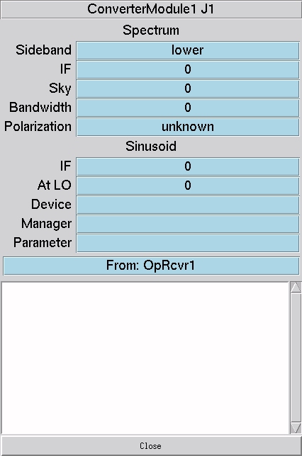
Blue Buttons:
On each of the screens for specific modules there
are blue buttons next to function selections that will open the IF
Manager screen information box
on that particular function. On screens controlling all the particular
modules the blue button opens a sub menu from which a specific input, output
or function information screen can be chosen. Information such as
where the signal on that particular input or output is coming from or going
to, frequency, bandwidth, polarization of that signal and the manager controlling
that function is available on a screen like this one:
All Modules Tab:
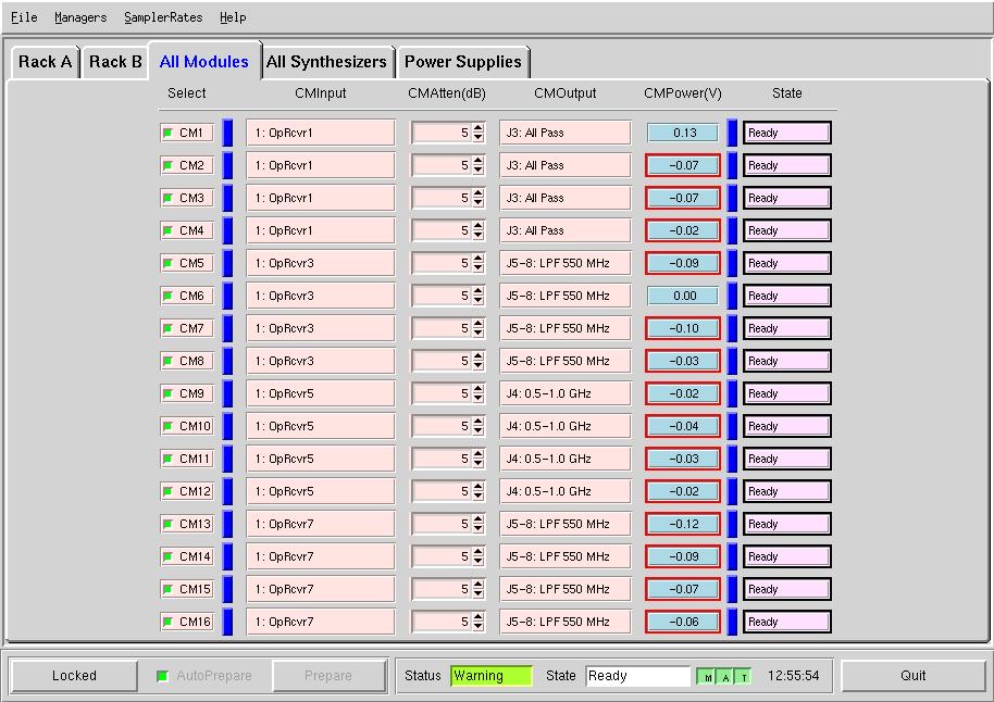
Clicking the All Modules tab allows the same access and control to all
Converter Modules that the four Converter pair tabs allow to the pairs
of Converters but without access to the information and control of the
synthesizer parameters.
All Synthesizers Tab:
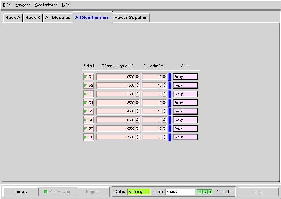
Clicking the All Synthesizers tab allows the user to control the frequency
and output power levels of all eight synthesizers similarly to the control
over individual dedicated synthesizers in the synthesizer box on the Converter
pair screens. Frequency resolution is 1 kHz, level resolution is
0.1 dB, but it is recommended that the RF level be set for +10 dBm for
best operation.
Power Supplies Tab:
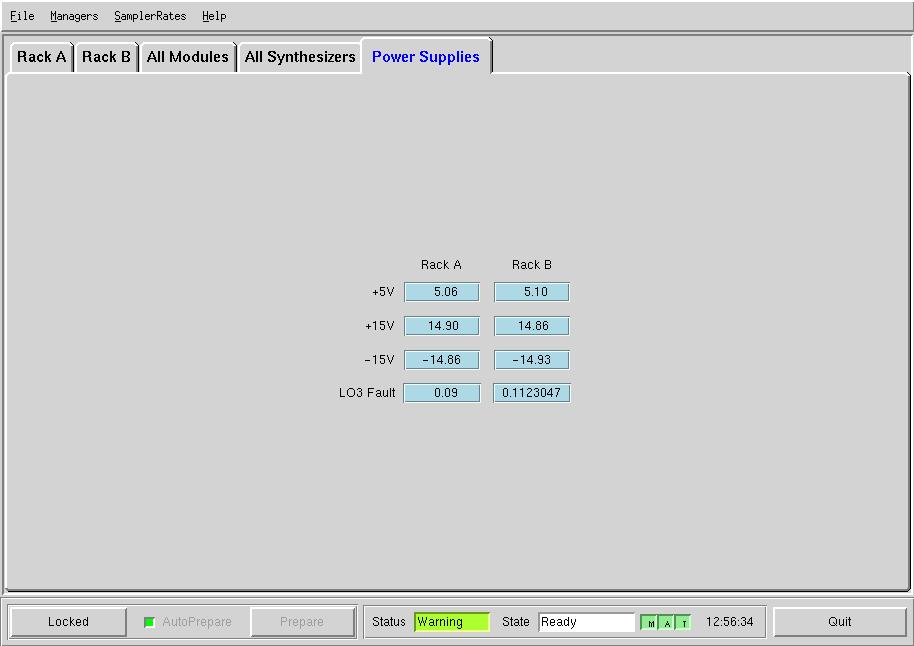
The power supplies tab gives the user the power supply voltages and
indications if LO3 is faulty.
Online
Technical Documentation Link
|