 NRAO Skynet 20-meter telescope
Details for various kinds of observing projects
Making Images
Preamble -- For those not familiar with radio astronomy, note that the 20-meter telescope is like a
camera with one pixel, which we call a "beam". To make an image, one must scan the telescope back and forth
across the object and build up an image, pixel by pixel, a process called mapping.
- Raster scans
- The 20-meter can do two types of mapping: raster (i.e., back and forth), or daisy patterns.
- The raster scans come in 2 flavors: "RALongMap" or "DecLatMap".
- Mapping is in either RA/DEC or Galactic Latitude/Longitude coordinates depending on the coordinate type selected in the Target screen.
- RaLongMap: sweep along the Right Ascension (or Longitude) direction, and step sucessive sweeps in Declination (or Latitude).
- DecLatMap: sweep along the Declination (or Latitude) direction, and step sucessive sweeps in Right Ascension (or Longitude).
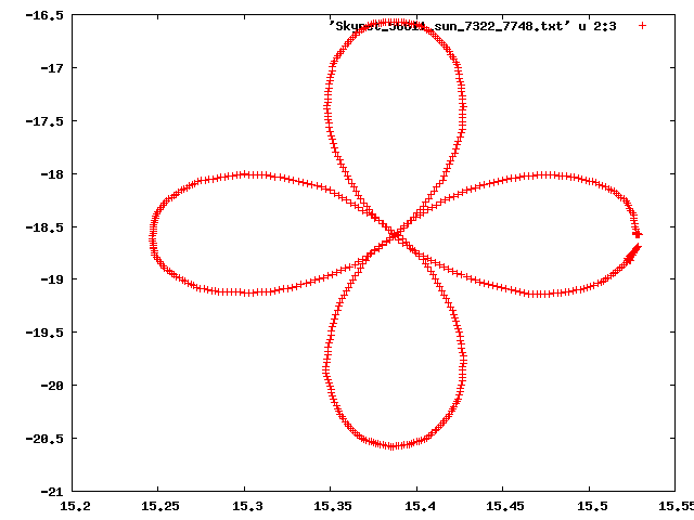
- Daisy: scan in a flower-petal pattern with the object of interest at the center.
Beamwidth -- The beamwidth of a telescope is given by Bw = 1.2λ/D (in radians).
in which λ is the observing wavelength, and D is the telescope diameter.
If you use the frequency in GHz (Fghz) instead of wavelength, then the
beamwidth in arcminutes is:
Bw = 62/Fghz (for a 20-meter telescope)
- The 8-10 GHz receiver has a beam size of about 7 arcmin.
- The 1.4 GHz receiver has a beam size of about 44 arcmin.
- The 1.4 GHz receiver is presently on the telescope.
General Advice -- Maps should be at least 5 beamwidths across, otherwise you cannot
distinguish the object from the background.
- For the 1.4 GHz receiver, the beam is about 44 arcminutes, so raster maps should be no
smaller than 4x4 degrees; and daisy maps should have a radius of 2 degrees or more.
Cautions:
- Blocking near the horizon: Use a minimum elevation somewhat higher than the default 5; there is blockage in certain directions near the horizon. The horizon is less blocked to the south; for far south sources such as the galactic center, the minimum elevation of 3 degrees will probably be ok.
- Also, due to the radiation from the atmosphere, mapping near the horizon shows the variations in system temperature due to the atmosphere, which may drown out the brightness from weaker sources. Best to use a minimum elevation of 25 degrees when doing maps.
- The 20-meter can pick up radiation from the Sun in its far sidelobes. To avoid this try to keep all parts of a map at least 15 degrees away from the Sun. In the Skynet interface, set the "Solar Separation" to 15, unless you really want to observe the Sun.
Quick Advice
For the 20cm receiver (installed as of Aug 2013)
Here are some rules of thumb that will get you pretty good maps.
    Set the minimum elevation to 25 degrees
    Set the solar separation to 15 degrees

Daisy Pattern:
-----------------
  1. use a radius of at least 90 arcminutes.
  2. number of petals: 4 for a quick look,
      8 or 12 petals for an reasonable image of the central part of the field.

  3.  For Radius:
       up to 180 arcmin -- use 45 sec per petal
        200-300         -- use 75 sec per petal
        300-400         -- use 100 sec per petal
        (above that use radius divided by 10)

     Multiply these times per petal by the number of petals
     to get the total duration.

  4. use integration time of 0.2 seconds in all cases.


Map pattern:
--------------
  1. "Map Size" : Use a size of 6x6 beam widths or larger.

  2. "Sampling Density" :
	Set the gap between sweeps to 1/4 for average maps
	Set the gap to 1/5 for higher quality.

  3.  Under "Map Depth"
	Select "integration time"
	Look at the Slew Speed: this should be 0.6 or less.
	Put integration time = 0.3 seconds.
	Then check the Slew Speed, if greater than 0.6,
		increase the integration time in steps of 0.1
		until slew speed is less than 0.6

Happy mapping!
|
Some Example Setups
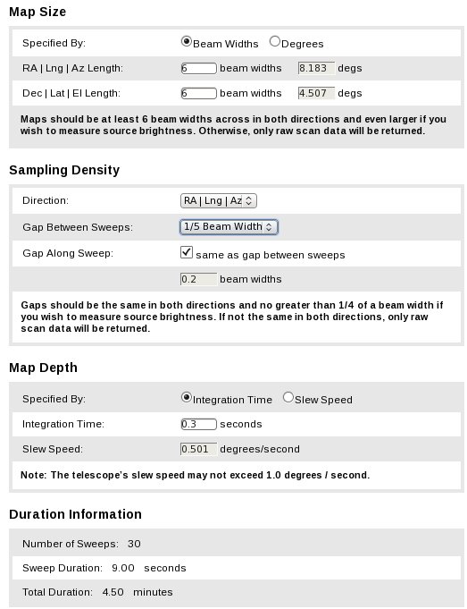
Quick, pretty good raster Map.
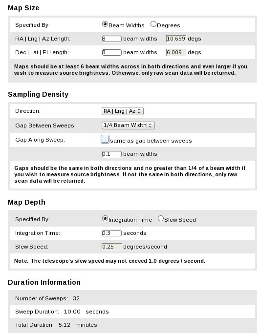
| Larger, better quality Map.
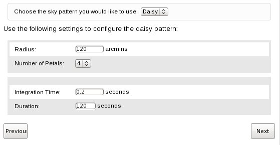
| Daisy: quick look
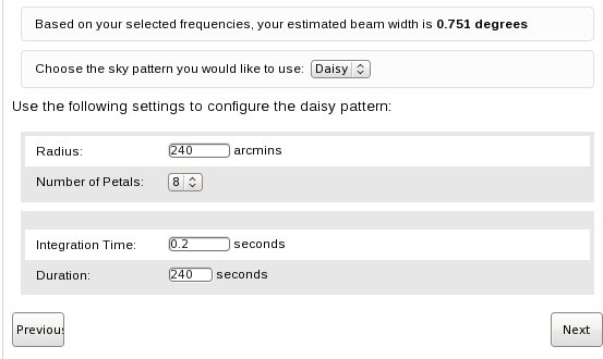
| Daisy: larger and denser
|
Lots of gory details and calculations follow, if you are interested --
Link to: Daisys - Sweeps
Daisy Scans
The daisy scan is specified in Skynet by four parameters:
- The Radius (R) in arcminutes
- The number of petals (Np)
- The Integration time (Tint) in seconds.
- The total duration (Tdur) in seconds.
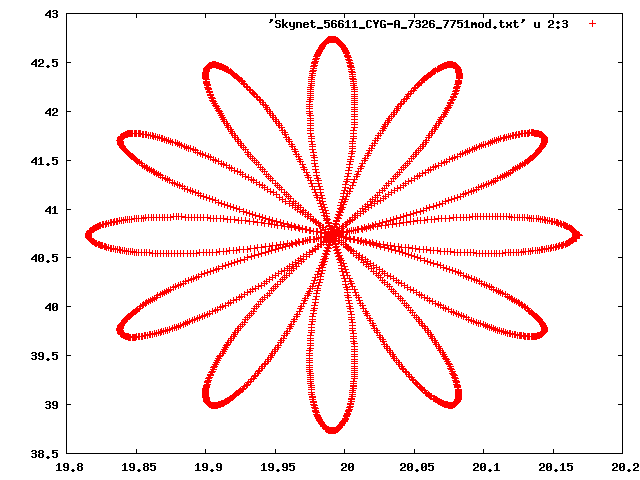
| 4-petal daisy scan | 12-petal daisy scan |
|---|
 |  |
How Large a Radius?
The radius depends on the size of the region of interest, and, as mentioned above, a minimum
radius of 2-3 beamwidths is desirable. Thus, a good choice would be the size of the object
to be observed plus 2 beamwidths.
How Many Petals?
For a quick look, the 4-petal pattern is sufficient. This gives one a measurements of the
peak brightness of the object as the telescope scans through the center. This is good for
"point sources", i.e., ones with angular diameter less than about half of the beam width.
For sources whose angular sizes are several beam widths across, one can use more petals
in the pattern to make an image of the object. But note that the daisy pattern is more dense
near the center than at the edges, so one gets a more detailed image nearer the central part
of the pattern.
For a fully sampled map one needs the data points to be spaced closer than a half beamwidth.
One can estimate the size of the fully sampled part of a daisy scan by the approximate
formula :
Rfs = radius of fully-sampled area = 0.5BeamWidth/tan(360degrees/2Np)
In general if you are interested in a detailed image of an extended object,
the raster scan (RALongMap or DECLatMap) is a better choice.
This table shows the approximate radius of the fully-sampled area for various choices of Np
and observing frequency.
| Frequency | Beam Width | N petals | Radius of fully-sampled area |
|---|
| 1.4 GHz | 44 arcmin | 4 | 22 arcmin |
| 1.4 GHz | 44 | 8 | 54 |
| 1.4 GHz | 44 | 12 | 84 |
| 1.4 GHz | 44 | 20 | 142 |
| .......... |
| 8.5 GHz | 7.5 arcmin | 4 | 4 arcmin
|
| 8.5 GHz | 7.5 | 8 | 9
|
| 8.5 GHz | 7.5 | 12 | 14
|
| 8.5 GHz | 7.5 | 20 | 23
|
How much time?
As the telescope sweeps across the source, the quality of the data depends on the
number of samples per beam width. One needs at least 3 samples per beam; we will adopt
"good", "better", or "best" the choice of 3, 5, or 9 samples per beam (Nsb).
The time spent on each sample is the specified integration time, Tint.
Typically the minimum Tint is 0.1 seconds.
- The total time per beam (product of Nsb and Tint) determines how faint an object
can be detected.
- The speed at which the antenna must move is given by Va = Bw /(Nsp*Tint) in arcmin/second.
- For the 1.4 GHz receiver, with a 43 arcmin beam, the antenna speed given by that
formula can be quite large. We limit the speed to about 30 arcmin per second to avoid
exceeding the capabilities of the telescope.
- The angular distance the telescope must move to trace out one petal is approximately
2.5 to 3 times the radius of the daisy pattern. We will use the factor of 3 for a
conservative estimate.
Thus:
- Time to sweep around one petal = Tpetal = 3R/Va
- Total time for the whole pattern = Tdur = Np * Tpetal
Adopting some values for "good", "better", or "best" quality:
good: Tint = 0.1 sec, Nsb=3 samples/beam
better: Tint = 0.2 sec, Nsb=5 samples/beam
best: Tint = 0.3 sec, Nsb=9 samples/beam
| Examples for 1.4GHz observing (44' beam) |
| Radius | Npetals | Quality | Tint | Nsb | Time per petal | Tdur |
| 120' | 4 | good | 0.1 | 3 | 30 sec | 120 sec |
| 120' | 4 | better | 0.2 | 5 | 30 sec | 120 sec |
| 120' | 4 | best | 0.3 | 9 | 45 sec | 180 sec |
| ..... |
| 300' | 4 | good | 0.1 | 3 | 60 sec | 240 sec |
| 300' | 4 | better | 0.2 | 5 | 60 sec | 240 sec |
| 300' | 4 | best | 0.3 | 9 | 90 sec | 360 sec |
Due to the limit in maximum telescope move rate of 40'/sec, there is no difference between
the "good" and "better" cases.
A complication arises due to the cosine elevation factor in the maximum slew rate.
If you want more than 4 petals, just multiply the Tdur by Npetals/4.
Raster (or sweeping) Scans
The raster map is specified in Skynet by several parameters:
- Map Size
- Sampling Density
- Map Depth
Near the bottom of the screen is "Duration Information", which gives the number of sweeps, duration, and total map duration, depending on what numbers have been put in.
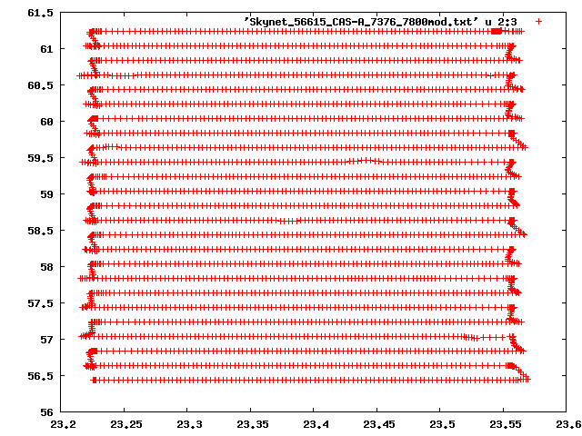
Here is a plot of a typical back-and-forth sweep pattern.
Map Size
Map Size may be given in either "beam widths" or "degrees". The best choice is to use beam widths. If you want the map to be equal angular size in both dimensions, specify equal number of beams in both RA and DEC.
Sampling Density
- Direction: may be either "RA|Lng|Az" or "DEC|Lat|El"
- This goes along with the choice of Coordinate Type in the Skynet "Choose Center Coordinate" screen.
- RA and DEC is used for mapping if the coordinate type was "RA/Dec".
- An alternate is to set the coordinate type to galactic longitude and latitude --
- but this is difficult to make work properly, so for now we will just use RA and DEC.
- If type is "RA|Lng|Az" the sweeps are in the RA direction, spaced by steps in the DEC direction.
- If type is "DEC|Lat|El" the sweeps are in the DEC direction, spaced by steps in the RA direction.
Gap between sweeps: in units of the beam width. Usually use 1/4 or 1/5. One may use larger fractions such as 1/3 and 1/2 for quick maps of extended sources such as galactic plane areas.
Gap along sweep: normally check the box so that this is the same as the gap between sweeps.
- The images we display on the web site may look better if you set the gap along sweeps to 0.1 instead of the default.
Map Depth
Set the integration time to 0.2 seconds, then check the Slew Speed. If the slew speed is greater than 0.6 degrees per second, increase the integration time in steps of 0.1, i.e., try 0.3, 0.4, etc, until the Slew Speed is 0.6 or less.
If you select "Slew Speed", then you can set the slew speed in the box, and it will set the corresponding integration time.
The relation between Slew speed, Integration time, and Gap is as follows:
Given Gs = gap along sweep; Beam Width = BW (in degrees);
tint = integration time in seconds; Sslew = slew speed in degrees/second.

Then :  Sslew x tint = Gs x BW

Given any two of the quantities Gs, Sslew, tint, the third one can be calculated.

The time to do one sweep is Tsweep = Length (in degrees) / Sslew.
At the bottom of the page, note the number of sweeps, the sweep duration, and the total duration of the map. Generally you are discouraged from making maps that take more than 30 minutes or so to complete. If you want to map a very big area, it is more efficient to make several smaller maps.
[Frank D. Ghigo, NRAO-Green Bank, Nov 2013, rev Jan 2014, rev March 2015]