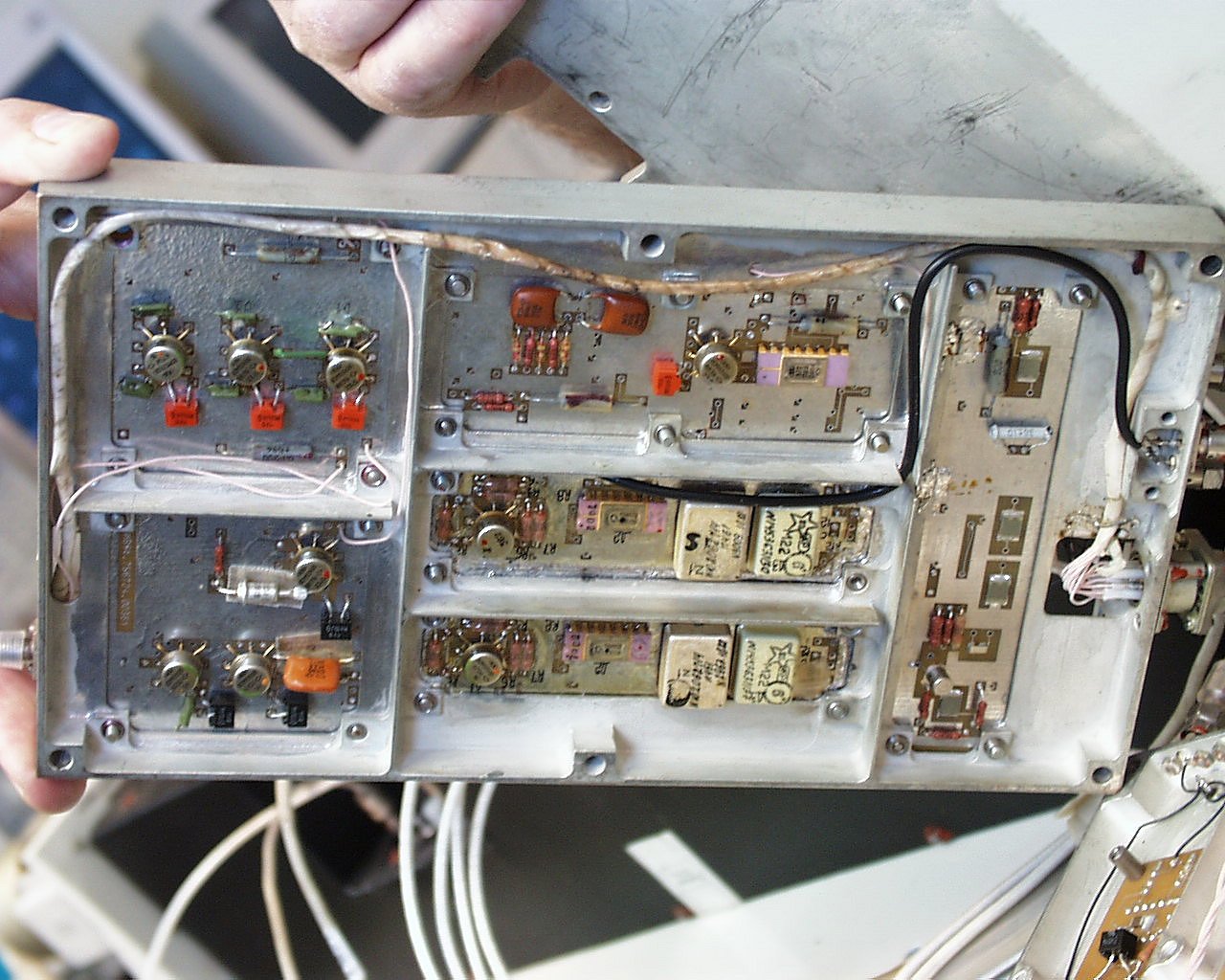
A full description of the VIRK can be found in [3]. Here we highlight some
of its contents:
![]() 8 GHz band uplink waveguide A/B switch.
8 GHz band uplink waveguide A/B switch.
![]() 2 LNAs.
2 LNAs.
![]() 2 receivers.
2 receivers.
![]() 2 swept PLLs.
2 swept PLLs.
![]() 2 locked reference generators.
2 locked reference generators.
![]() 2 8 GHz band downlink exciters.
2 8 GHz band downlink exciters.
![]() 2 power amps.
2 power amps.
![]() 15 GHz band multiplier/exciter chain.
15 GHz band multiplier/exciter chain.
![]() QPSK modulator with data buffer.
QPSK modulator with data buffer.
![]() Traveling wave tube amplifier.
Traveling wave tube amplifier.
![]() 15 GHz band A/B waveguide switch.
15 GHz band A/B waveguide switch.
![]() Command decoder and power supplies.
Command decoder and power supplies.
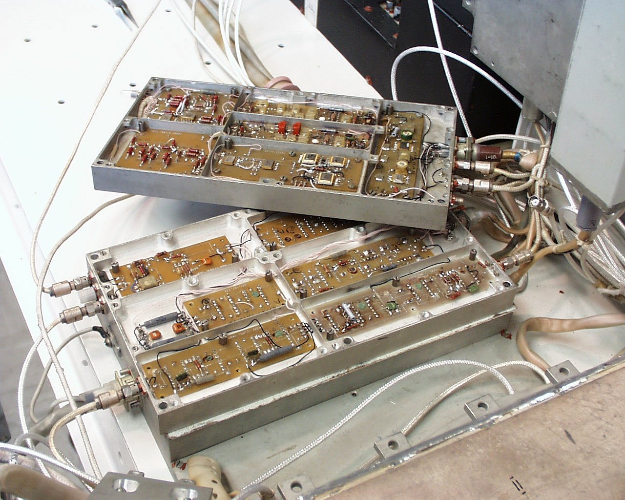
The system is designed to have two of everything, thus the A/B waveguide switches. There were two complete 8 GHz band up and down link systems, but only one 15 GHz band exciter/modulator/amplifier. The Russians have plans to add a second 15 GHz band system to the VIRK module. A fan panel was used under the traveling wave tube amplifier part of the VIRK to cool the 15 GHz band system.
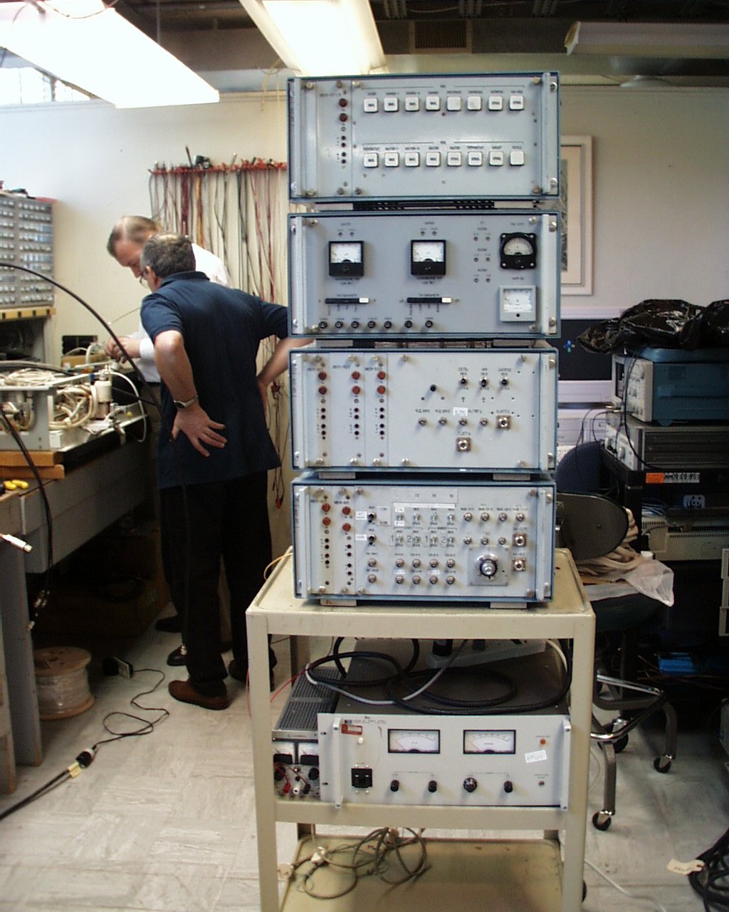
The command generator is used to produce serial commands to the VIRK to change its mode. This module is shown in Figure 2 as the module that is on top. The command generator initially had problems upon arrival in Green Bank. This unit was opened up in the lab and revealed that it was designed using only relays (about 30 bipolar latching relays) and did not contain any solid state logic. These relays could be heard operating in order to produce the serial bit streams.
This module provides meters that read various VCO outputs of the transponder and transmitter and other controls and power levels of the VIRK. It is the module next to the top in Figure 2.
The VIRK signal source generates a 7.2 GHz uplink test signal, and contains the 14.71 MHz crystal oscillator used to drive the transmitters. The module is the forth module from the top in Figure 2.
This module is a QPSK demodulator that did not include clock recovery. The clock was provided directly from an external source provided from teh 3.765 GHz stage of the 15 GHz transmitter. The demodulator also does not contain any carrier recovery.
This module is a Russian brand 50 watt-meter used to monitor the 15 GHz band system. It has a digital readout.
The RadioAstron system receives an uplink CW reference at 7.215255 GHz, transmits a downlink timing carrier at 8.472960 GHz (both referred to here as 8 GHz band), and a data signal at 15.063040 GHz (15 GHz band) which is QPSK modulated with 18, 36, or 72 MHz clock rates. An internal reference frequency of 14.710 MHz is used to lock all frequencies to the received 8 GHz band uplink.
When the RadioAstron modules are first turned on there is a 2 hour wait for the system to ``warm-up''. This is to allow the 14.71 MHz crystal oscillator to reach frequency stability and to also allow the traveling wave tube amplifier to stabilize.