
GBT 4mm Receiver Project Book
Chapter 6
IF Processing
Author: Roger D. Norrod
6.1 Introduction
A brief description of how the 4mm receiver fits into the GBT common IF system is provided in Chapter 3, and details of the front-end block downconverters are given in Chapter 5. This chapter concentrates on details of the frequency converters following the front-end, and restrictions on observing modes that result.
6.2 Millimeter Converters
The 2-26 GHz IF outputs of the 4mm receiver front-end connect to an existing subsystem called the Millimeter Converters (MMC). The MMC hardware consists of five boxes attached to the receiver turret. One box contains a LO amplifier, LO level monitor, and a 4-way power splitter to distribute the MMC LO signal (generated by the LO Rack LO1B synthesizer). This LO box also contains a M&C interface to provide MMC switch control and monitoring. The remaining four identical boxes contain circuitry to process IF signals. Figure 6-1 shows a simplified RF block diagram of the MMC system.

Figure 6-1 Millimeter Converter Block Diagram (Click on image for higher resolution pdf)
The MMC allows selection of a portion of the 2-26 GHz first IF to be connected into the 1-8 GHz bandwidth of the GBT common IF system. Table 6-1 gives the sky frequencies corresponding to each MMC filter selection, for three values of the front-end LO frequency. Please note that in the case of FL2, FL3, or FL4 selection, the 4-8 GHz IF filter in the MMC down-converter imposes a 4 GHz instantaneous bandwidth restriction. For example, with FL3 selected and LO1 = 66 GHz, any 4 GHz portion of the 79-86 GHz range can be passed to the IF Router, selected by tuning the MMC LO frequency.
It can be seen that the MMC subsystem imposes constraints on the simultaneous placement of spectral windows. For example, it is not possible to simultaneously observe the SO2 lines at 69 and 84 GHz in the same receiver channel.
Table 6-1: Sky Frequency Range vs. MMC Filter Selection
| MMC Filter | LO1 = 65 GHz | LO1 = 66 GHz | LO1 = 67 GHz |
| FL1 2-8 GHz | 67-73 GHz | 68-74 GHz | 69-75 GHz |
| FL2 7-14 | 72-79 | 73-80 | 74-81 |
| FL3 13-20 | 78-85 | 79-86 | 80-87 |
| FL4 19-26 | 84-91 | 85-92 | 86-93 |
Table 6-2 gives the MMC LO ranges and sidebands corresponding to the filter selected.
Table 6-2: MMC LO Range and Sideband vs. Filter Selection
| MMC Filter | MMC LO | Sideband |
| FL2 7-14 | 15-18 GHz | Lower |
| FL3 13-20 | 9-12 | Upper |
| FL4 19-26 | 15-18 | Upper |
6.3 Equipment Room IF System
The MMC outputs are connected via coaxial cable to the IF Rack on the receiver turret. The IF Rack contains an IF router network, amplification, equalization, level set attenuators, filter selection, and then analog intensity modulates the IF signals onto optical fibers for transmission to the GBT Equipment Room in the Jansky Lab. Figure 6-2 shows a simplified RF block diagram of connections in the Equipment Room relevant for each of the four 4mm Receiver channels.
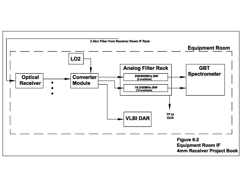
Figure 6-2 Equipment Room IF Connections (Click on image for higher resolution pdf)
The Optical Receiver modules contain photodiode detectors to demodulate the intensity modulated optical signals, buffer amplifiers, and 4-way power splitters that allow up to four 1-8 GHz Converter modules to be connected to each IF from the telescope. The Converter modules perform an up/down conversion for high image rejection, and multiple switched output ports to drive various data acquisition backends. The LO2 frequency is set to tune the desired input frequency to an appropriate output frequency for the particular backend in use. For example, the VLBI DAR outputs operate at the standard VLBA IF range of 500-1000 MHz.
The GBT Spectrometer will be used for spectral line observations. Like all GBT receivers, the number of IF drawers and samplers provided for the Spectrometer will place limits on the number of spectral windows that can be observed with the 4mm Receiver. Eight total 200 or 800 MHz bandwidth windows are available; two could be placed on each of the four front-end channels, or four on two of the front-end channels, for example. Sixteen total 16.5 or 50 MHz windows are available so up to four could be placed on each of the four front-end channels. Of course, the MMC tuning and instantaneous bandwidth constraints discussed in Section 6-2 also place constraints on the simultaneous frequency locations of spectral windows.
