|
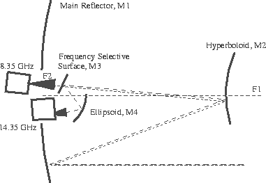
Figure 1:
Optics geometry for Green Bank Earth Station. The main antenna surface, M1,
is left, the sub-reflector, M2, is below the prime focus.
The frequency selective surface (FSS), M3, is above the 8.35 GHz horn.
and the ellipsoidal mirror, M4, is above the 14.35 GHz horn.
Both the 8.35 and 14.35 GHz
horns view the same region of the sky simultaneously.
|

|
Figure 2:
Schematic diagram showing the organization of data sampling
for the 4 Sessions comprising the GPA survey. Samples are taken
9 times a second, every 2.4\arcm. Sections are labeled by the
center galactic longitude (degrees).
|
|
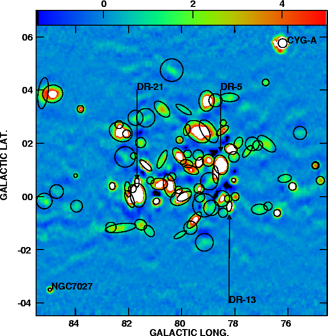
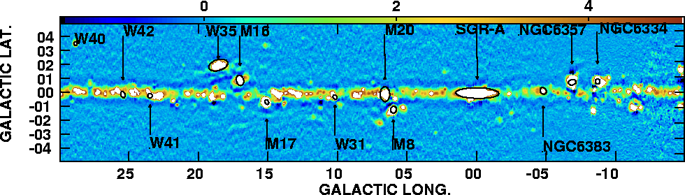
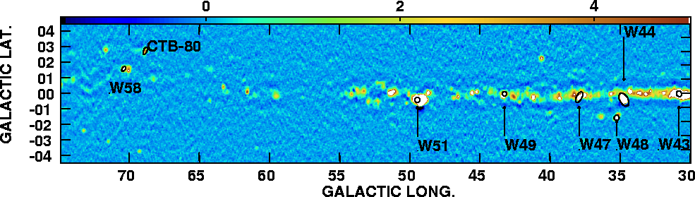
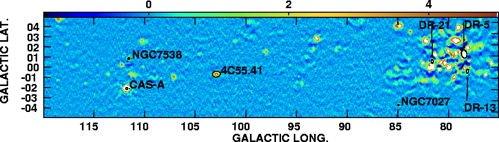
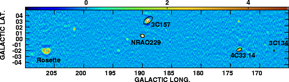
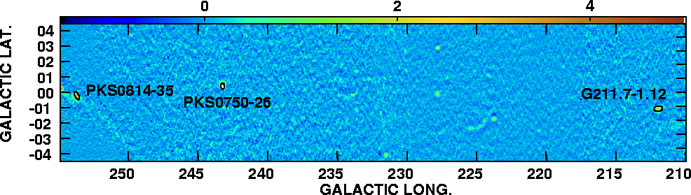
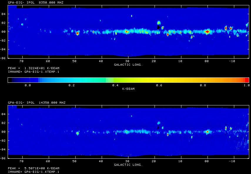
Figure 3a:
The 8.35 GHz image of the Cygnus Loop Region of galactic plane,
showing calibration sources
Cygnus A (north west), DR21 and NGC7027 (south east).
The flux density range shown is -1.5 (dark blue)
to 5 (red) Jy.
Sources brighter than 5 Jy are shown in white and noise features
more negative than -1.5 Jy are shown in black.
|
| |
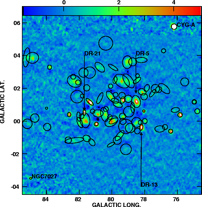
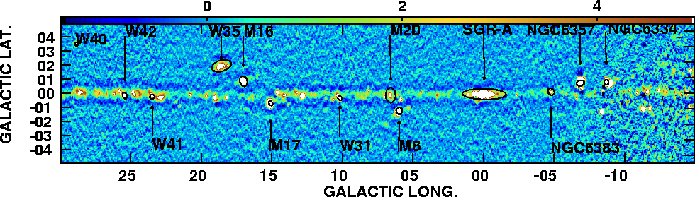
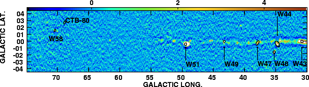
|
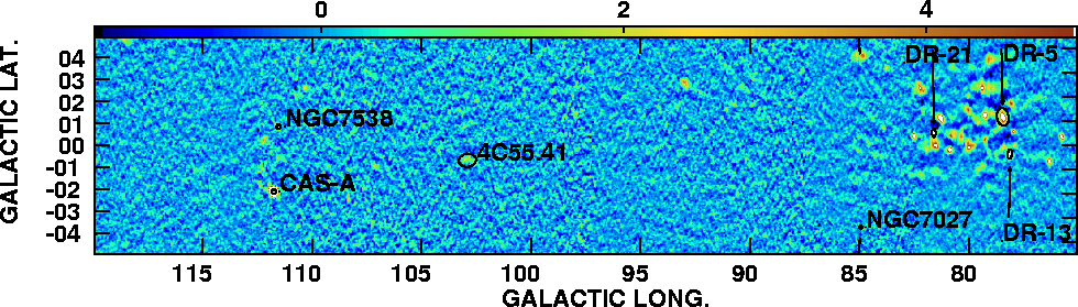
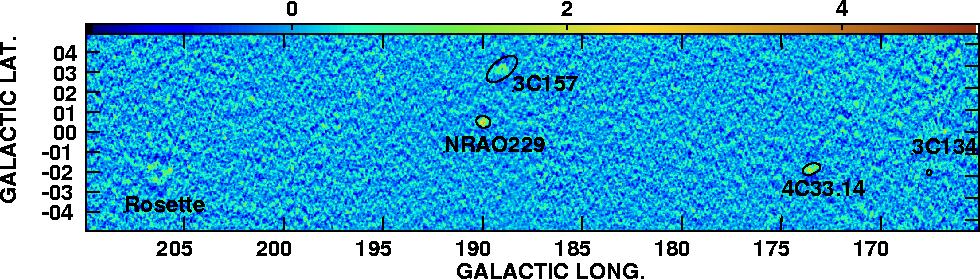
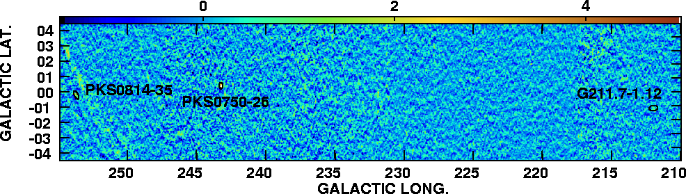
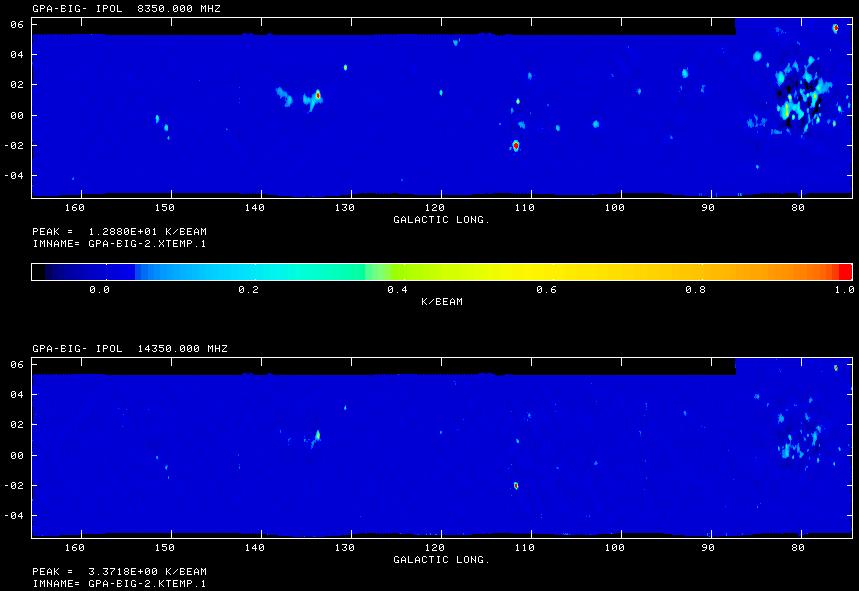
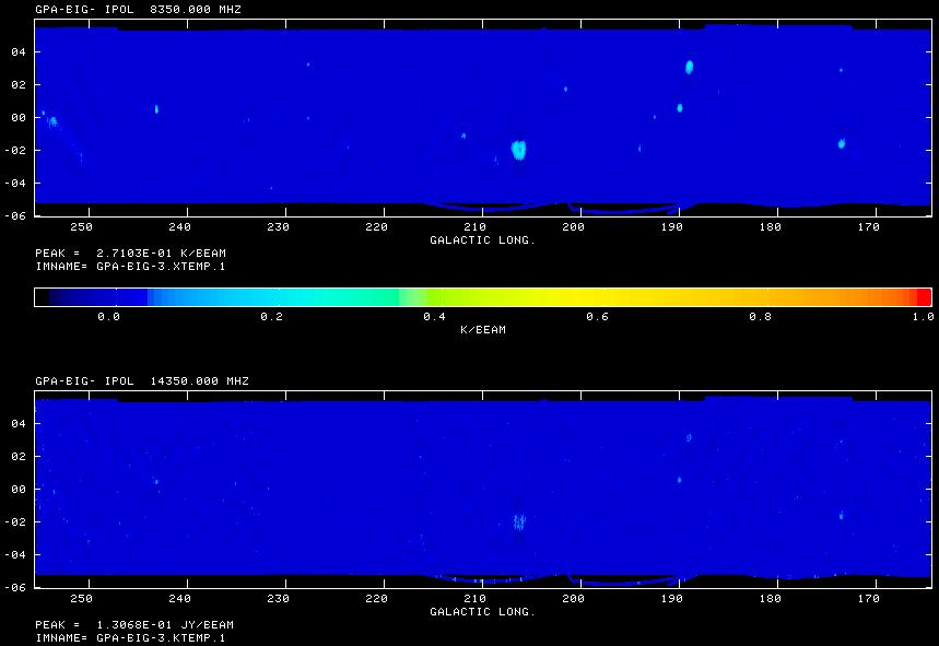
Figure 3b: The 14.35 GHz image of the Cygnus Loop Region.
The de-convolved source size is shown with ovals,
scaled by a factor of two for clarity. Upper limits on the source
size are shown as circles. Due to source confusion along
the galactic plane, source labels are located at b = 4 degees for
sources with b > 0 and labels are located at b = -4 degrees
for sources with b < 0.
(Zoom in on the color 8.35 GHz and
14.35 GHz images.)
|