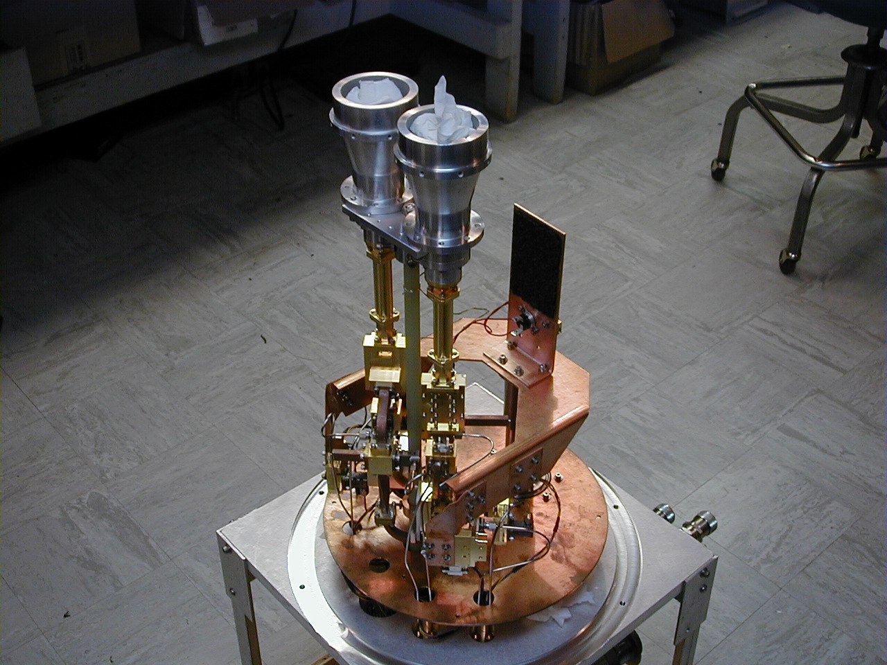
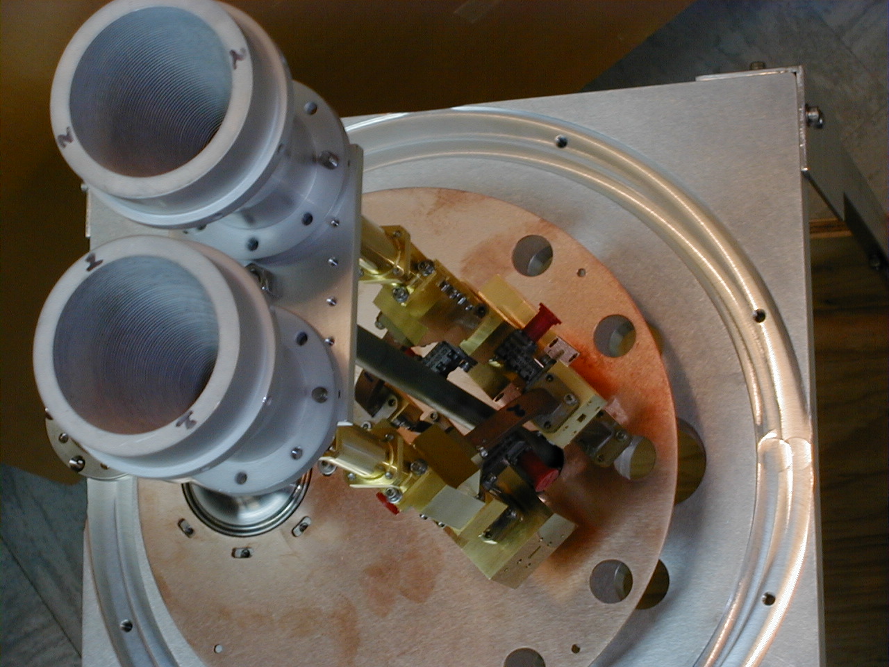
From the top: Feed horns, phase
shifters, OMTs, Cal couplers
and hybrid tees, no amplifiers, cold straps or cabling yet.
Looking down, slightly off axis.
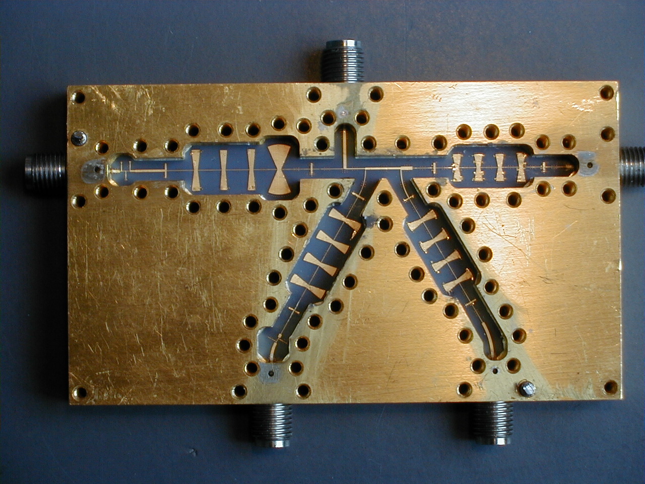
NRAO Frequency
Multiplexer
Microstrip frequency multiplexer, overall width=3.3 inches.
Note tuning bonds on radial stub (bow tie) elements.
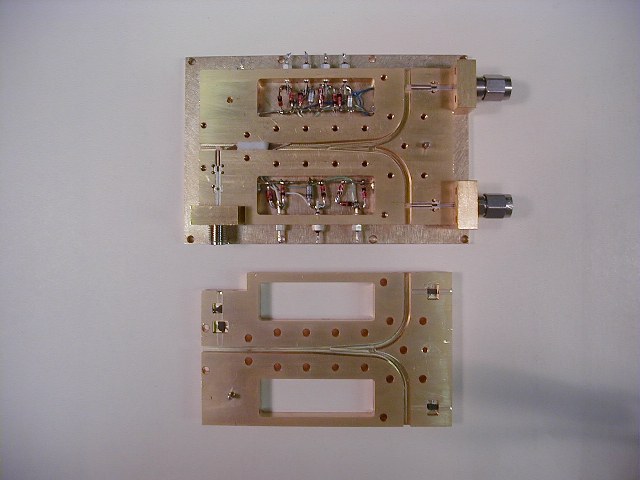
44 GHz Local Oscillator
Multiplier
This triples 14.6667 GHz from the GBT LO1 to 44.0 GHz, then divides and amplifies
for two outputs. The upper item is the MMIC circuit half, the lower item is the
lid. The
input is at the lower left of the MMIC
half where the 14.6667 GHz enters via a female connector, is amplified and
then multiplied to 44.0 GHz. The waveguide acts as a high pass filter to block
the second harmonic at 29.333
GHz and has an
attenuator (a pointed piece under the white foam) to keep the
later amplifiers from saturating and to improve matching. The signal
is then split in waveguide, each side of the split is further amplified and
the
resulting two 44.0 GHz L.O. signals are brought out via male connectors. The 44.0 GHz
energy is coupled in to and out of the waveguide by microstrip to waveguide
probe transitions. Note the absorber in the amplifier clearance cavities, the little
black pieces in the
lid. The diodes in the rectangular cavities act as transient protection on the
bias lines for the
MMICs. Not
shown are the small blocks that cap the ends of the waveguide.