Appendix: GBT Gregorian Receivers
The Gregorian receivers are mounted in a rotating turret in the receiver
room located at the Gregorian Focus of the telescope. The turret
has 8 portals for receiver boxes. All 8 receivers can be kept cold
and active at all times. At present, the antenna must be moved to the
access position (elevation = 77.67°) to rotate the turret.
A future upgrade is planned that
will allow the turret to be re-positioned at any elevation angle.
Basic information on each Gregorian receiver is summarized
in the following table. Specifics on each receiver, including
calibration data, follow the table.
| Receiver |
Center f(GHz) |
Fsky (GHz) |
waveLen(cm) |
FWHM |
est.Tsys |
IF1 (GHz) |
| 1-2 GHz |
1.45 |
1.15 - 1.73 |
21 |
9' |
20 K |
3.0 |
| 2-3 GHz |
2.16 |
1.73 - 2.60 |
14 |
5.8' |
20-24 K |
6.0 |
| 4-6 GHz |
4.90 |
3.95 - 5.85 |
6.1 |
2.5' |
25 K |
3.0 |
| 8-10 GHz |
9.00 |
8.00 - 10.10 |
3.3 |
1.4' |
21-27 K |
3.0 |
| 12-15 GHz |
13.70 |
12.00 - 15.40 |
2.2 |
54" |
24-30 K |
3.0 |
| 18-26 GHz (1) |
20.00 |
18.00 - 22.50 |
1.5 |
37" |
38 K |
6.0 |
| 18-26 GHz (2) |
24.20 |
22.00 - 26.50 |
1.2 |
30" |
42 K |
6.0 |
| 40-50 GHz |
46.00 |
40.00 - 52.00 |
0.65 |
16" |
35-160 K |
6.0 |
Click in the "Receiver" column for further information about each
receiver.
Note that the 40-52 GHz receiver will not be
available until mid 2001.
Future receivers are planned for the 26-40 GHz band and the
68-116 GHz band, but will not be available for about 1-2 years.
The nominal frequency range for each receiver is listed in the
"Fsky" column. The choice of bandpass filters for each receiver,
as listed below under the individual receivers, allows the
nominal range to be exceeded slightly in some cases.
The receiver performance may be considerably worse beyond the
nominal frequency range, so please consult the calibration data
before attemping to observe beyond the nominal range.
1-2 GHz Receiver (1.15 - 1.73 GHz)
This receiver uses a cooled HFET amplifier. It has one beam on the
sky, with dual polarizations. The feed is a corrugated horn with
cooled OMT producing linear polizations. The user can select
circular polarization which is synthesized using a hybrid in the
front-end. Allowed internal switching modes are frequency and/or
polarization switching. The user can select one of four RF filters:
1.1-1.8 GHz, 1.1-1.45 GHz, 1.3-1.45 GHz, 1.6-1.75 GHz. The
calibration is by noise injection, with a choice between two levels.
Calibration data
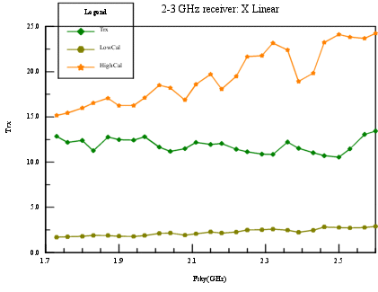
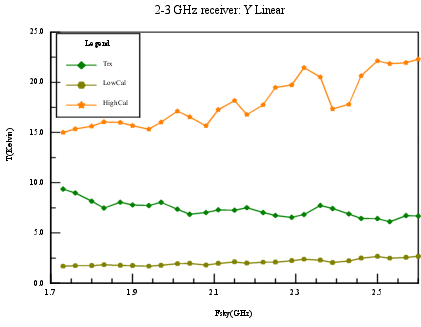
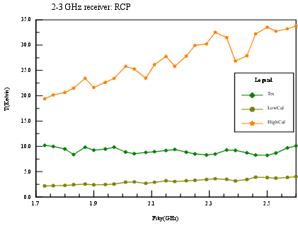
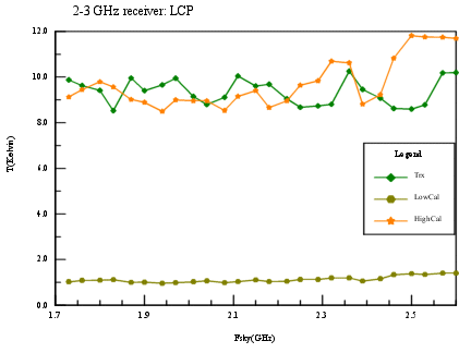
2-3 GHz Receiver (1.73 - 2.60 GHz)
This receiver uses a cooled, HFET amplifier. It has one beam with
dual polarizations. The feed is a corrugated horn with cooled OMT
producing linear polarizations. The user can select circular
polarization synthesized using a hybrid in the front-end. Internal
switching modes include frequency and/or polarization switching.
The user can select one of two RF filters: 1.68-2.65 GHz, 2.1-2.4
GHz. Calibration is by noise injection, with a choice between two
levels.
Calibration data
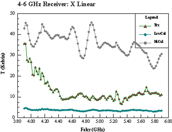
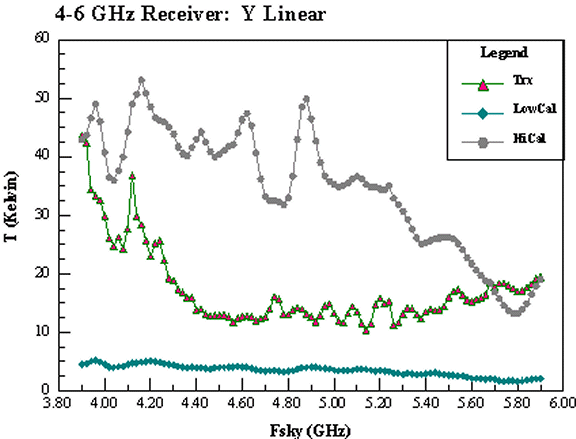
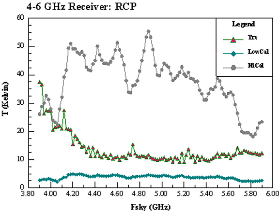
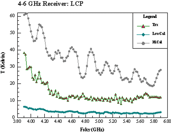
4-6 GHz Receiver (3.95 - 5.85 GHz)
This receiver uses a cooled, HFET amplifier. It has one beam, with
dual polarizations. The feed is a corrugated horn with cooled OMT
producing linear polarizations. The user can select circular
polarization synthesized using a hybrid in the front-end. The allowed
internal switching mode is frequency switching. The user can select
one of four RF filters: 3.9-5.9 GHz, 3.95-4.65 GHz, 4.55-5.25 GHz,
5.15-5.85 GHz. Calibration is by noise injection, with a choice
between two levels.
Calibration data
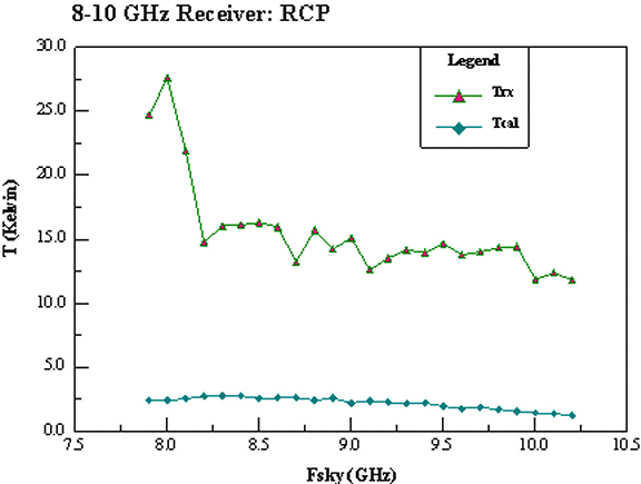
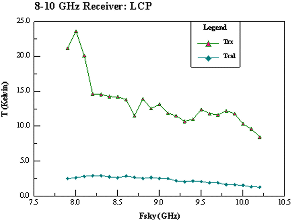
8-10 GHz Receiver (8.0 - 10.1 GHz)
This receiver uses a cooled, HFET amplifier. It has one beam, with
dual circular polarizations. The feed is a corrugated horn with cooled
polarizer producing circular polarizations. The internal switching
mode is frequency switching. The user can select IF Bandwidth of
500 or 2400 MHz. Calibration is by noise injection.
Calibration data (Preliminary)
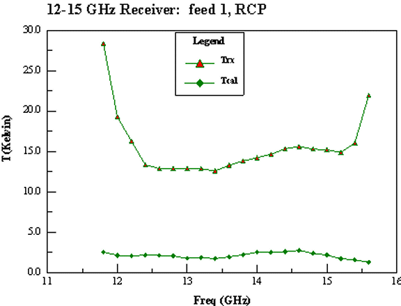
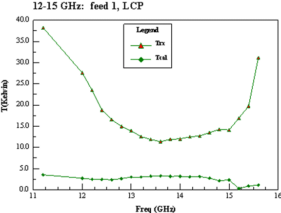
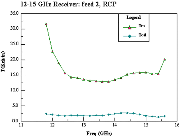
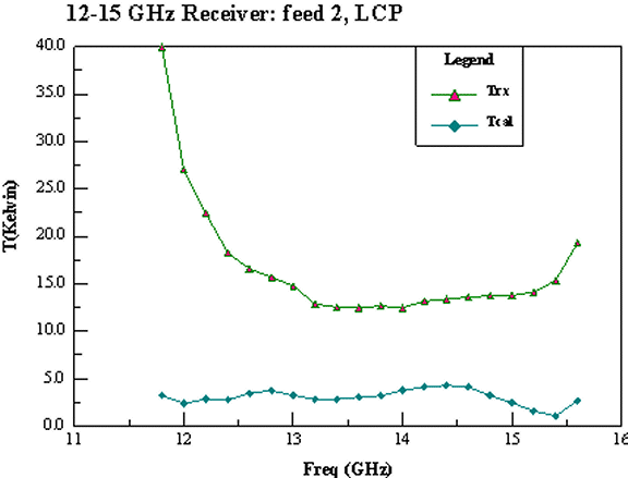
12-15 GHz Receiver (12.0 - 15.4 GHz)
This receiver has two beams on the sky with fixed separation, each
with dual circular polarization. The feeds are corrugated horns with
cooled polarizers producing circular polarizations. Internal switching
modes are frequency and/or feedhorn beam switching. The user
can select IF Bandwidth of 500 or 3500 MHz. Calibration is by noise
injection.
Calibration data
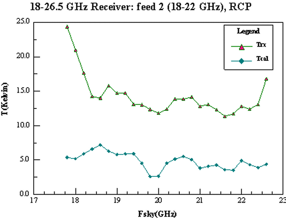
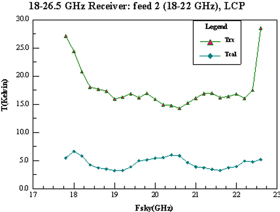
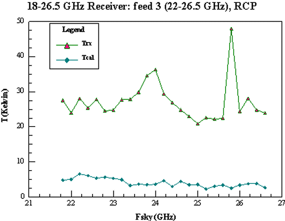
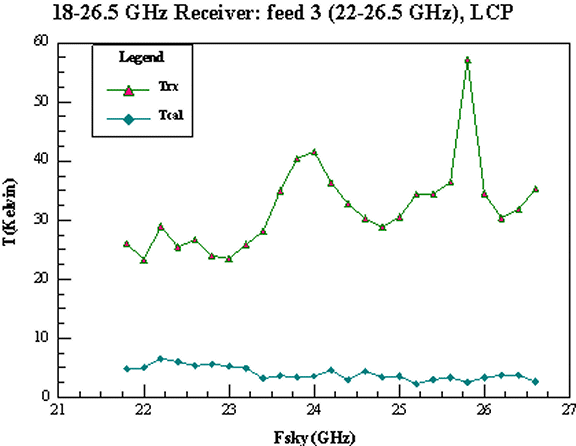
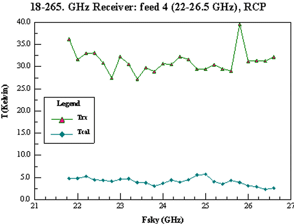
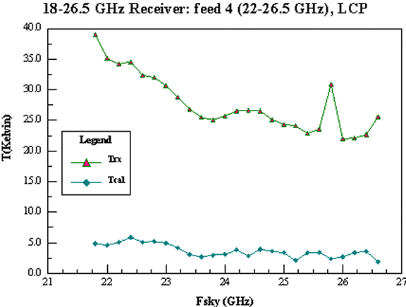
18-26 GHz Receiver (18.0 - 26.5 GHz)
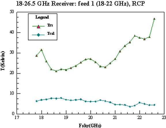
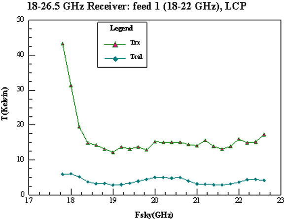
This receiver has four beams total, each with dual circular
polarization. One pair of beams cover the 18-22.4 GHz band with
fixed separation on the sky. Two other beams cover the 22-26.5
GHz frequency range, also with fixed separation on the sky. The
feeds are corrugated horns with cooled polarizers producing circular
polarizations. Internal switching modes are frequency and/or
feedhorn beam switching. Calibration is by noise injection.
Calibration data
40-50 GHz Receiver (40.0 - 52.0 GHz)
This receiver has four beams with fixed separation, each dual
circular polarization operating over 40-52 GHz. The four feeds are
oriented in a cross. the feeds are cooled corrugated horns with
cooled polarizers producing circular polarizations. The internal
switching modes are frequency switching and feedhorn beam
switching. The IF Bandwidth is 4000 MHz. Calibration is by noise
injection and/or ambient load. A tertiary beam chopper is planned for
this receiver but will not be available before late 2001.


