TWT Control Module
The Two Way Timing (TWT) Control Module consists of 7 major sub-assemblies.
The TWT module generates two frequencies, 1) an uplink frequency at IF
(around 28 MHz for VSOP)
provided to the TWT Transmitter Module and 2) a predicted downlink
frequency at IF.
The IF input signal is downconverted from around 600 MHz to around 12 MHz
by the combination of the 500-800MHz synthesizer and Image Reject Mixer.
The downcoverted signal is provided to the phase detector module
for comparision with the predicted downlink by the phase detector module.
The phase detector output is provided to the micro processor board.
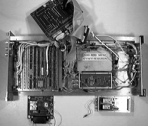
The exploded view of the TWT module (above) shows the MCB interface module
at the top (upside down). The processor board is to the left. One of the
DDS boards is shown at the bottom left. The synthesizer sub-assembly is
installed at top middle of the module. The image reject mixer is installed
in the bottom middle. The Phase detector sub-assembly is removed from the
right section of the module and shown at the bottom right.
The sub assemblies are described in detail below, including the status
of spares at the sub-assembly level.
This module was designed, micro-programmed and constructed by Larry D'Addario.
MCB Interface (No Photo)
Control of the TWT module is via the standard VLBA MCB interface. The
uplink and downly frequency predictions are communicated via the MCB.
The 10 Filtered phase residuals are transmitted to the station computer
via the MCB once per second.
Because this sub-assembly is unchanged from the VLBA design, and used
in most OVLBI modules, it is described elsewhere.
Two spares are in stock.
Processor board
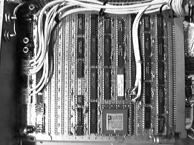
The TWT micro processor is on a wire wrap board. The micro processor
updates the two DDS frequencies 5000 times a second. The wire-wrap board
contains samplers of the phase detector output.
One spare needed, none assembled.
500-800 MHz Synthesizer (No Photo)
The 500-800 MHz Synthesizer can be tuned in 10 MHz steps. The synthesizer
output is provided to twt Image Reject Mixer.
One spare needed, none assembled.
Image Reject Mixer 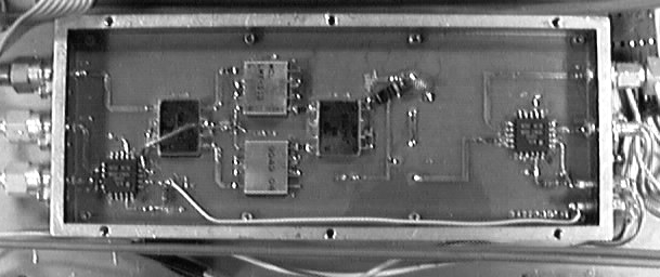
The Image Reject Mixer down converts the satellite IF center frequency
into the input frequency range required by the phase detector module.
One spare needed, none assembled.
Phase Detector 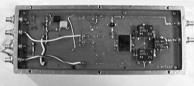
The Phase Detector sub-assemble compares the satellite IF center frequency
with the predicted IF frequency synthesized by the downlink DDS. The
analog output of the phase detector module is provided to samplers on the
processor board.
One spare needed, none assembled.
DDS Boards (2) 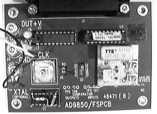
There are two Direct Digital Synthesizer boards (DDS) in the TWT Control
module, one for calculating the uplink frequency and one for the downlink.
The uplink IF frequency is provided at IF (about 28 MHz) to the TWT Transmitter
module for upconversion. The downlink frequency is provided to the
phase detector module.
Three spares needed, three assembled.
Related Web Sites
Return to the OVLBI Hardware Page or the
OVLBI Home Page.
VSOP/HALCA has a home page.
The
VLBA Correlator
NRAO Socorro is developing other hardware and software for the
NASA OVLBI project.
There is a
Space VLBA Correlator
home page as well.
Return to the Station Software Guide.
The National Radio Astronomy Observatory
(NRAO)
is a facillity of the
National Science Foundation
operated under cooperative agreement by
Associated Universities, Inc.
glangsto@nrao.edu Last update: 98 January 16