The following four images were produced using the new AVS "network", which allows the displaying of lines in the structural model as tubes while simultaneously displaying the "quads" (four-sided polygons) which are also present in the original dataset.
Click on any of the images to see a larger version.
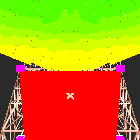
 This first scene is looking almost straight down, from the tip of the prime
focus boom (i.e., the focal point of the primary), toward the roof of the
feedroom and the inner edge of the big dish. We see that the line of sight
to the innermost panels passes close to the front top edge of the room, and
that the proposed rangefinders will be even further from the edge of the
beam. The tubes projecting from the top of the feedroom are modelling the
turret, and the secondary focal point. Note how the new AVS network has the
curious side-effect that the lines are rendered along the axes of the tubes.
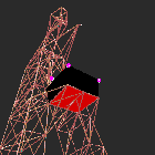
 The second scene is an oblique view of the feedroom area from below. The
prime focus boom and the subreflector actuator model are above the room, and
there are four 0.5 m cubes on the edges of the roof of the feedroom,
representing suggested locations for the rangefinders.
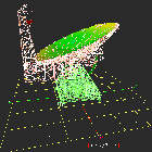
 The third scene is an overview of the telescope model from the side, as seen
from several hundred meters distance and a height of about 100 meters. There
are 18 cubical objects in the scene, with sides 20 inches (0.5 m) long. The
telescope is pointing at the zenith. The pseudocoloring of the panels of the
dish is coding the magnitude of the displacement vector of the nodes due to
gravity acting on the dish. The grid spacing 1000 inches.
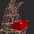
 The fourth scene is another oblique view of the feedroom area, but this time
from a point at about the same height as the room. In this scene the two cubes
at the rear corners of the feedroom have been moved downward and outward
slightly, so that they are at the edge of the roof, and about a meter from the
front of the feed legs.