Building and Using an Itty Bitty Telescope |
|||||||
 |
|||||||
|
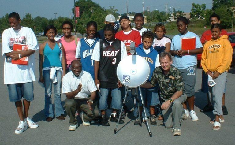
David Fields with his IBT and a group of students in Memphis TN
|
|||||||
|
Download this pdf for instructions on making an IBT using an RV kit. These can be purchased from Ebay for about $70 and contain every thing you need, except a power supply: You get the dish, a tripod, the tuning meter, and plenty of co-ax! |
|||||||
|
The "Itty Bitty Telescope" or IBT was fashioned after the Little Bitty Telescope described at http://www.setileague.org/articles/lbt.pdf. The original IBT was designed by Chuck Forster who is with the Society of Amateur Radio Astronomers. It was improved by Kerry Smith. For a classroom lesson using the IBT, see: http://www.aoc.nrao.edu/epo/teachers/ittybitty/ |
|||||||