 Green Bank Telescope Construction ProgressGreen Bank Telescope Construction Progress
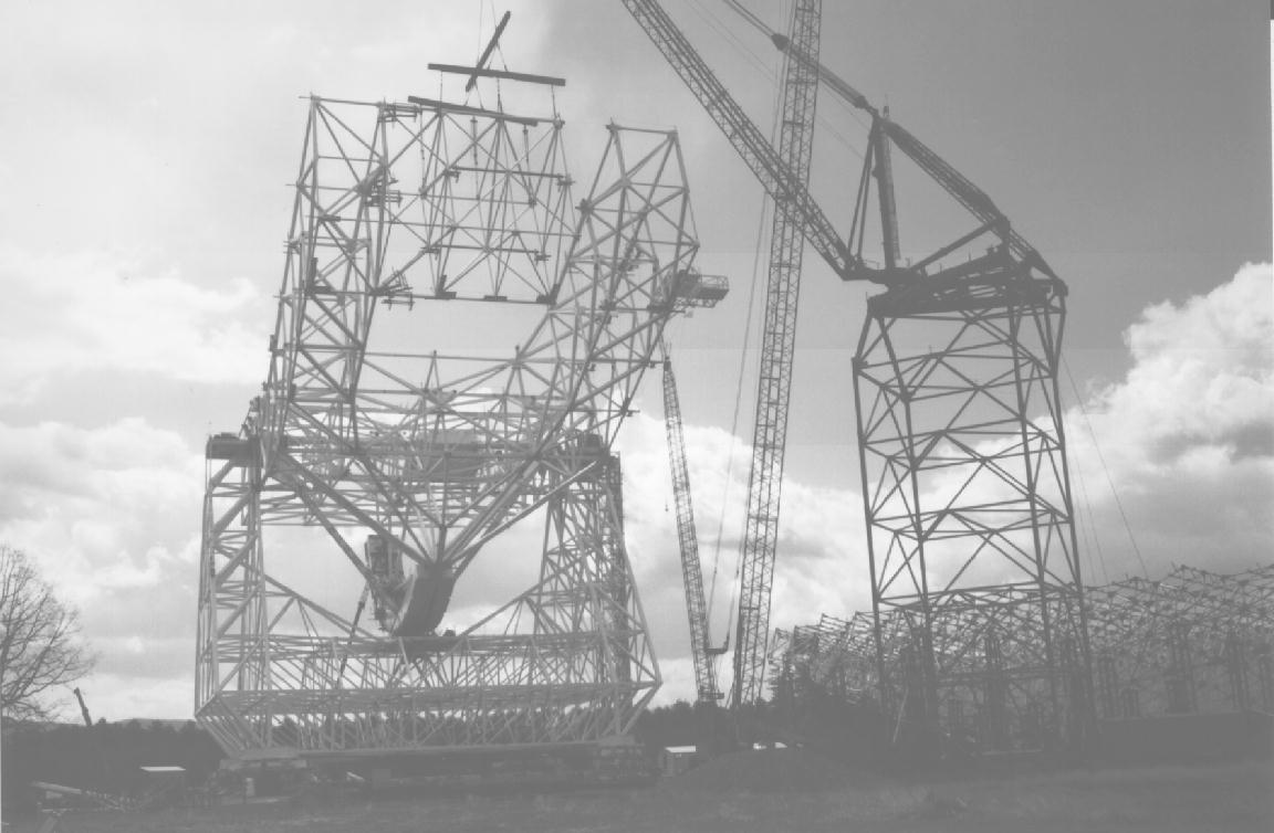
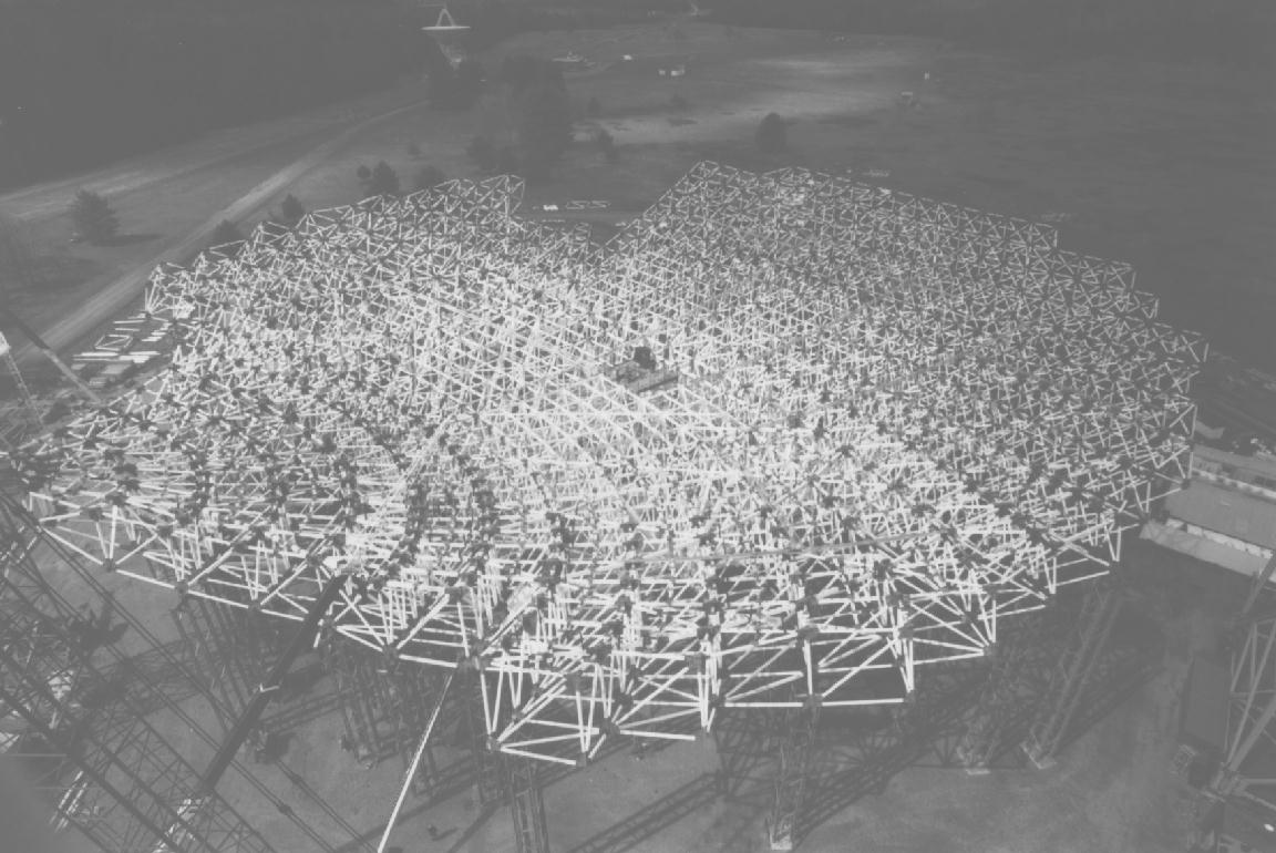
The first photograph shows the filling in of the end of the horizontal feed arm, and the second photograph shows that the back up structure (BUS) is nearing completion in trial erection on the ground.


The first photo shows the antenna rotated 180 degrees from the October photo. The right side of the horozontal feed arm is completed. The second photo of the back up structure (BUS) shows the hoops are completed from 33 out to the end of the right side.

The first photo shows that the box structure is completed and work has started on the right side of the horozontal feed arm. The second photo shows the back up structure (BUS) in trial erection with the vertex tower and shack in the foreground. The BUS is 50% complete. The completed portion runs from hoop 15 to 33, yet to be done are from hoop 0 to 15 and from 33 to 45. The third photo is of the east side of the site with the 140-foot radio telescope in the background on the left. The photo shows the top 60 feet of the vertical feed arm. The 8-meter subreflector is in place and the prime focus boom is show near its down position.
This photo shows from left to right:
The box being installed around the elevation shaft. The box consists fo five trusses going from front to back parallel to the counter wights and set between and above the support legs. The fourth truss is being installed in the back half.
All six of the large 36-inch square spokes are now in place. Sixteen of the twenty-two counterweight boxes are attached to the sector wheel. The center truss of the front half of the box is in place. Note that this photo is taken from the back of the tilting part of the antenna.
The elevation bearings and elevation shaft are in place and completed. Top and bottom beams of the box structure are attached to the elevation shaft. Five sections out of six of the sector wheel are in place with elevation gear racks attached. Four of the six large 36-inch square spokes are in place with the fifth being installed.
The 148-foot long, 200-ton elevation shaft is installed on the alidade. It was lifted in two halves and will be joined near mid-span. The box structure, which supports the reflector and feed arm, will be constructed around the shaft.
The elevation bearing tie shaft is being assembled on the ground. The truss structure surrounding the tie beam will form the box structure when complete. The box supports the reflector back-up and feedarm structures. Trial erection along the third axis has begun as shown.
The left hand tower of the alidade is finished being welded and has its base coat of white paint. The access platform still needs to be installed. The right hand tower is still being welded, but the right tower's access platform and equipment lift are installed to the bearing weldment. The shoring tower, seen in the center of the picture, for support of the elevation bearing tie shaft is installed on the third level.

The alidade is completely erected except for the 70 ton weldments which will rest at the top of the towers.
The right tower is finished to level 6 and the alidade has been rotated (slowly) 180 degrees to allow work on the other tower to proceed. A blanket of snow softens the features of the work site.
Alidade level four is complete. At the time of this picture work was in progress on the "tee-pee" section. The entire structure is now resting on its 16 wheels. The beginnings of the stairway and equipment lift can be seen on the left tower. This pictures allows a view of the 140' telescope on the right.
Alidade level three is complete with all four corner assemblies on the track. The structure is still resting on shoring towers. Welding is in progress.

The S-70 derrick is complete. The grouting of the azimuth track was finished over the winter. Two levels of the alidade are near completion supported by shoring towers. One corner assembly is erected onto the track.
Here the derrick tower is finished topped by a smaller "Clyde" derrick has been erected for assembly of the final S-70 derrick. Grouting of the azimuth track has begun.
The azimuth track has been installed, but not grouted. Assembly of the 180 foot derrick has reached the fourth level.
The concrete foundation is complete at this point. A section
of the northeast ring is covered for use as a ramp.
In the foreground the American 9299 crane is being assembled
while in the background the foundation for the four legs of
the derrick tower is being constructed.
On the left are the pillars which will be used for construction
of the tipping structure.