- LSTSTART
- This lists the calculated local sidereal time in sidereal seconds since
local sidereal midnight of the start time for the scan.
- SITELAT, SITELONG, SITEELEV
- Currently, these keyword values
are the location of the intersection of the azimuth and elevation axes
in the NAD 83 reference system. These values were provided by the GBT
metrology group. The current values are:
Longitude: tex2html_wrap_inline$79^&cir#circ;50^'23^''.406$ W (
 )
)
Latitude: tex2html_wrap_inline$38^&cir#circ;25^'59^''.236$ N (
 )
)
Height: 824.551 m
In the future, we may modify these to be ITRF values; in any event the
values may change as we refine our knowledge of the position of the
telescope.
- SITESYS, SITETYPE
- These keywords specify the coordinate system
(datum) in use for SITELAT, SITELONG, SITEELEV, and whether this is
a geodetic or geocentric system. The current values are `NAD83',
`GEODETIC'.
- INDICSYS
- This keyword describes the type of positions contained
in the MAJOR and MINOR axis columns of the binary table. Possible values
are GALACTIC, RADEC, HADEC, AZEL or OTHER. In the case of OTHER, the
MAJOR and MINOR columns will contain co-ordinates in the user-defined
system.
- OFFSYS
- Analogous to the INDCSYS keyword, this keyword describes
the command offset coordinate system.
- ORADESYS
- Analogous to the RADESYS, this specifies the standard
FITS keyword for the offset command coordinate system.
- RADESYS, EQUINOX
- For RADEC co-ordinate systems, the RADESYS
standard FITS keyword specifies the coordinate reference frame for the
MAJOR and MINOR axis columns. The EQUINOX keyword denotes the epoch in
use, for the MAJOR and MINOR axis columns. These are described in
detail in WCS paper II.
- DELTAUTC
- This specifies the UT1 - UTC offset, in use at the beginning
of the scan, in seconds of time.
- IERSPMX, IERSPMY
- These keywords specify the values of polar motion correction
in use at the beginning of the scan.
- PFM_CONF, PFM_VERS
- These keywords list the pointing focus model configuration name and version.
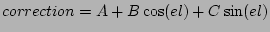
- REFMODEL
- The field lists the refraction model type. Values may be one of "NONE",
"GbtComMemo16", or "PTCS35.2", meaning refraction is off, based on GBT commissioning
memo 16, or PTCS note 35, version 2 respectively.
- MNTOFFAZ, MNTOFFEL
- These keywords specify the encoder offset values, applied by
the Az/El servo system (CCU). The values are in degrees.
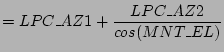
- LPC_AZ1, LPC_AZ2, LPC_EL
- These keywords specify the user provided local pointing correction values
for the scan in azimuth, cross-elevation and elevation respectively.
The net contribution to pointing by the local pointing
correction values can be computed by the relation:
- PNTMODEL
- This keyword defines the type of pointing correction model active during the scan.
The field currently has two values: 'GBT MEMO 173' or 'NONE'.
- PNTAZD00, PNTAZB01, PNTAZD01, PNTAZA11, PNTAZB11, PNTAZC21, PNTAZD21, PNTAZB02, PNTAZD02
- Theses keywords represent the values of the traditional model coefficients for
the azimuth axis. The values are in radians, are the coefficients are
listed in GBT memo 173.
- PNTELD00, PNTELC10, PNTELD10, PNTELB01, PNTELD01
- These keywords represent the values of the traditional model coefficients for
the elevation axis.The values are in radians, are the coefficients are
listed in GBT memo 173.
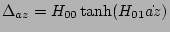
- PNTAZH00, PNTAZH01, PNTELH00, PNTELH01
- These keywords record the coefficient values for the hysteresis correction in azimuth and elevation.
The terms are defined in the following way:
 |
(7) |
Where  is the maximum amplitude of the correction in radians, and the term
  is the
multiplier of rate, used to control the engagement sensitivity. The term
is the
multiplier of rate, used to control the engagement sensitivity. The term  is in radians
per second.
is in radians
per second.
- PNTAZR00, PNTELR00
- These keywords represent the multiplicative coefficient of axis rate, used to derive a friction
correction. The term R00 is in units of radians of offset per
 .
.
- PNTLAMBDA1 ,PNTLAMBDA2, PNTLAMBDA3
- The keywords represent the average values of provided from the track correction
tables. The value is in degrees, and is an average value for the duration of the scan. For
concise definitions of these corrections, see PTCS PN-53, equation 48.
- FTRKXDA,FTRKYDA, FTRKZDA
- The GBT uses a focus tracking model of the form:
 |
(8) |
for each of the 3 displacement and 3 tilt axes.
This value indicates the position focus tracking constant coefficient in millimeters,
for the X, Y, Z axes.
- FTRKXDB,FTRKYDB, FTRKZDB
- The value indicates the cos(el) coefficient of the focus tracking model in millimeters.
- FTRKXDC,FTRKYDC, FTRKZDC
- The value indicates the sin(el) coefficient of the focus tracking model in millimeters.
- FTRKXTA,FTRKYTA, FTRKZTA
- This value indicates the focus tracking tilt constant coefficient in degrees,
for the X, Y, Z axes.
- FTRKXTB,FTRKYTB, FTRKZTB
- The value indicates the cos(el) coefficient of the focus tracking model in degrees.
- FTRKXTC,FTRKYTC, FTRKZTC
- The value indicates the sin(el) coefficient of the focus tracking model in degrees.
- LFC_X, LFC_Y, LFC_Z, LFC_XT. LFC_YT, LFC_ZT
- These keywords describe the local focus correction coefficients used during the observation.
Displacements are in millimeters, and rotations in degrees.
- DIABMODE
- This value indicates the state of whether or not diurnal
aberration corrections are active.
- POLARMTN
- This value indicates the state of whether or not polar
motion corrections are active.
- COSVMODE
- This value indicates the state of the cosVMode parameter.
- AMBTEMP
- Ambient temperature used for refraction calculations in degrees C
- AMBPRESS
- Ambient pressure used for refraction calculations in milliBars
- AMBHUMID
- Ambient humidity used for refraction calculations as a fraction (i.e. a range of 0..1.0)
- WEATHSTA
- This keyword describes the source of weather information, and may take on the values: User_Input, Weather_Station_1, or Weather_Station_2
- OPTICSMD
- This value indicates the optical path configuration of the telescope.
Values are 'PRIMEFOCUS OPTICS', 'GREGORIAN OPTICS' or 'STOW OPTICS'.
- FOCTRMOD
- This value indicates the state of the focusTrackingMode parameter.
Values may be either "OFF" or "ON".
- FOCPATM
- This value indicates the state of the parallacticAngleTracking
parameter. Values may be either "OFF" or "ON".
- TRCKBEAM
- This value indicates the ASCII name of the tracked beam.
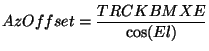
- TRCKBMXE
- This value indicates the cross-elevation offset in degrees,
with respect to the normal antenna boresight. In other words
this is the offset from the position which would have been used,
had the feed been placed in the center of the receiver mount.
Note that the actual azimuthal offset is elevation dependent,
and varies during a scan. The Az offset is defined as:
 |
(9) |
Note: This value is already accounted for in the (MAJOR,MINOR)
and (RAJ2000,DECJ2000) columns, and is included for reference only.
- TRCKBMEL
- This value indicates the elevation offset in degrees, with respect to
the normal antenna boresight. In other words this is the offset
from the position which would have been used, had the feed been
placed in the center of the receiver mount.
Note: This value is already accounted for in the (MAJOR,MINOR)
and (RAJ2000,DECJ2000) columns, and is included for reference only.
- PLSCALXT
- The keyword indicates the number of arc-min of the change in elevation per degree of subreflector X tilt.
- PLSCALZT
- The keyword indicates the number of arc-min of the change in cross-elevation per degree of subreflector Z tilt.
- SDMJD
- Describes the time associated as the center of scan, in
modified Julian day format.
- SOBSC_AZ, SOBSC_EL
- This keyword records the refracted topocentric
azmuth/elevation command at the scan midpoint. (Time indicated by the SDMJD keyword.)
This position is relative to the position of the beam on the sky, rather than
the position of the main reflector. Values are in degrees.
- SMNTC_AZ, SMNTC_EL
- These keywords records the encoder azimuth/elevation command
at the midpoint of the scan. (Time indicated by the SDMJD keyword.)
The values are in degrees, and are representative of the commanded
position of the structure with respect to the track, rather than a beam
position on the sky.
- DYN_ENA
- This keyword describes whether the antenna manager is
enabling external corrections.
- SDYN_AZ1,SDYN_AZ2,SDYN_EL
- These keywords record the dynamic pointing
correction in effect for azimuth, cross-elevation and elevation respectively
at the midpoint of the scan. Values are recorded in degrees.
- SDYN_FTKYP
- This keyword records the Y-axis dynamic focus correction
in effect at the midpoint of the scan in millimeters.