
GBT 4mm Receiver Project Book
Chapter 4
Calibration and Optics
Authors: David T. Frayer, Galen Watts
Calibration
Summary
The 4mm calibration document (pdf) linked here discusses the specifications and calibration plan for the GBT 4mm receiver. The specification to maintain better than about 3% relative calibration of the instrument drives the calibration strategies and design of the instrument. We plan to adopt a three load calibration system (cold, ambient, and sky). By using the cold and ambient loads we can accurately calibrate the system gains and expect relative calibration uncertainties on the derived T_{A}^{*} antenna temperature scale of order 1--3%. With the addition of the sky-load, we can monitor the weather conditions and verify the self-consistency of the calibration solution with the adopted opacity and atmospheric temperature.
Calibration Specifications
- Short-term gain stability -- A short-term gain stability of the receiver output in volts shall be better than 1% over times of less than 10 seconds.
- Long-term gain stability -- The receiver drifts shall be well behaved such that one can calibrate out the drift for time scales of at least 10 minutes from a simple linear interpolation between two measurements to better than 1%. The long-term gain stability of the instrument will determine how often calibration scans are needed.
- Relative antenna temperature scale -- The conversion of measured instrumental volts into the antenna temperature scale corrected for atmospheric attenuation (T'_A) shall be measured to 3% accuracy. This specification reflects the repeatability of making relative measurements with the instrument. The output temperature scale of the GBT data taken with the 4mm receiver shall be in units of T_A^{*}, but this 3% accuracy specification is explicitly for T'_{A} and does not include our ability to measure ohmic losses and rearward spillover and scattering (i.e., eta_l).
- Absolute temperature scale -- The derivation of the telescope-independent absolute temperature scale depends on measurements of planets of known brightness and the derivations of several telescope efficiencies. The calibration goal is to provide absolute calibration at the 15\% level. This specification implies that we need to measure the effective main-beam efficiency ($eta_{mb} = eta_c*eta_{fss}) with an accuracy of 15%; T_{mb} = T_{A}^{*}/eta_{mb}.
Monitor and Control Specifications Associated with Calibration
- The control system shall be able to move the optical table to place the sky, a cold load, and an ambient load into each of the two beams.
- The control system shall be able to move a quarter-wave plate into one of the beams for VLB circular polarization.
- The 4mm system needs to support the DCR, spectrometer, GUPPI, and VLB backends. The DCR backend will be used for pointing, focus, and occasional tipping observations. Only one beam of the 4mm system will be used for VLB observations.
- The system shall be able to collect the data from the
calibration
sequence for each of the supported backends. The cold and ambient
loads are 180 degrees apart on the table and can be alternated between
the two beams. A typical calibration sequence will consist of the
following:
- Sky observations in both beams (off source)
- Ambient-load observations in beam 1 and cold-load observations in beam 2
- Ambient-load observations in beam 2 and cold-load observations in beam 1
- The data collection shall include the following:
- Data stream connected to current backend
- Position of the optical table
- Cold-load temperature sensor
- Ambient-load temperature sensor
- Outside temperature
- The overheads associated with saving the data and moving the wheel shall be less than 50% of the total time of the calibration sequence.
Calibration Document for the GBT 4mm Receiver (pdf)
Optical Table
The Optical Table primarily consists of a disc placed parallel to and a small distance above the top of the receiver. It rotates on an axis through the center of the disc and the midpoint between the two receiver feed horns. The disc has six equally spaced holes through the surface parallel to the top of the cryostat giving the disc the appearance of a spoked wheel. The holes are cut such that with disc rotation they can be positioned over the feed windows. Four holes are open to allow both feed horns to receive radiation from the telescope optics when the disc is properly positioned. The fifth hole is covered by a mirror angled such that with a second, angled mirror above the center of the disc the feed below the fifth hole views a 20K absorber load inside the cryostat when the disc is rotated to the proper position. The sixth hole in the disc, opposite the fifth hole, is covered with an absorber load to provide a 300K source for the second feed when the first feed is viewing the cold load. Both loads have temperature sensors reporting to the Monitor and Control system (M+C). The disc can be rotated to place either load above either feed or place unblocked holes over the feeds.
Calibration Optics
Figure 4-1 shows the design of mirrors used to translate the feedhorn phase center (F1) to a focus above the cold load (F2). Two identical 90 degree offset paraboloid mirrors intercept a cone from the focal point with half-angle of 22 degrees. Measured feedhorn pattern integrations indicate that 92% (at 68 GHz) to 98% (at 92 GHz) of the pattern power is contained within the 22 degree cone. A Physical Optics analysis concluded that the mirrors will do an effective job. The effective cold load temperature will be determined in laboratory noise measurements using liquid nitrogen and ambient absorbers. The 20K cold load is machined from Emerson & Cuming MF110, and a diode temperature sensor will be used to monitor the physical temperature.
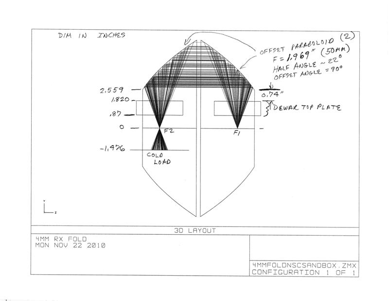
Figure 4-1: Calibration Cold Load Mirrors
Figure 4-2 shows an Inventor model of the optical table with the two mirrors mounted. The mirrors have been fabricated of aluminum on a NC milling machine. Opposite the left mirror is an inverted cone 12cm diameter and 2cm high holding the ambient absorber made from Cuming Microwave LF-72 foam. From network analyzer measurements, the absorber return loss is approximately 25dB across the band.
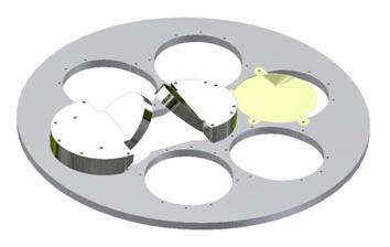
Figure 4-2: Optical table with calibration components.
