
GBT 4mm Receiver Project Book
Chapter 3
General Configuration
Author: Roger D. Norrod
3.1 Microwave
The 4mm Receiver front-end hardware consists of a cryostat package and associated room temperature electronics, mounted in one of the GBT Receiver Turret positions at the Gregorian focus. Figure 3-1 is a simplified block diagram of the microwave portion of the front-end and the major components are briefly described below. More details are provided in following chapters.
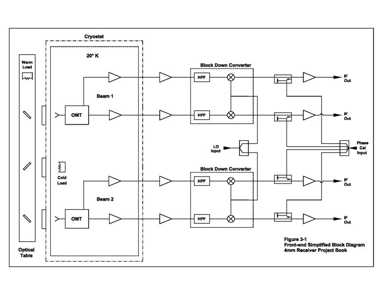
Figure 3-1: Front-end Simplified Block Diagram (Click on image for higher resolution pdf)
More detailed block diagram (PDF)
3.1.1 Optics
The cryostat uses a standard Gifford-McMahon closed cycle cryocooler to cool two corrugated feedhorns, two orthomode transducers (OMT), and four HFET low-noise amplifiers to less than 20K. The feedhorns are placed such that the two beams are at the same elevation on the sky, and are physically separated by 26.4 cm resulting in beam separation of approximately 4.7 arcmin. The OMTs provide orthogonal linear polarization, but a separate quarter-wave polarizer plate and insertion mechanism outside the dewar is planned to allow user selection of circular polarization in one beam for VLBI observations. The feeds illuminate the subreflector through quartz vacuum windows. (Ref NRAO EDIR 315.) The quartz windows incorporate matching layers to minimize reflections over the frequency range of interest.
An optical table sitting outside the windows is a motorized rotatable plate allowing any of several components to be placed between the vacuum windows and the subreflector. The table will be used to introduce calibration loads, and originally the plan was to incorporate the polarizer plate on the optical table. But it is preferable if the circular polarizer lies between the vacuum windows and optical table allowing use of the calibration loads in circular polarization, and this option is under investigation.
3.1.2 Calibration
Temperature scale calibration is an issue that has received much discussion. Currently the plan is to implement hot-cold load switching, using reflectors to illuminate a cold load inside the cryostat. The figure schematically shows the optical table placing reflectors in a position which terminates Beam 1 in a warm (ambient) load, while Beam 2 is directed off two reflectors through a third vacuum window to a terminating cold load on the 20K refrigerator station. Because the table is somewhat massive, the goal is to allow approximately 5 seconds to interchange the loads so hot-cold load switching will be relatively slow.
Ambient load-sky chopping using a spinning pinwheel was also considered, but it is thought the above system will provide superior results so load-sky chopping will not be implemented pending tests of the hot-cold calibration system. For similar considerations, and in order to simplify waveguide plumbing, incorporation of diode noise sources are not planned.
3.1.3 Microwave Components
The wideband waveguide OMTs are Boifot junctions similar to those described in NRAO EDIR 303. The cryogenic HFET low-noise amplifiers will be the best available at the time of construction. Following the cryostat will be additional amplification and commercial down-converters followed by a coupler for phase cal injection (see below), and IF amplification. The IF signals then proceed by coaxial cable into the GBT common IF system as described below.
Block down-converter assemblies were purchased in conjunction with the precursor 3mm receiver project and because of the significant cost the plan is to use these in the 4mm receiver. They were specified for 68-92 GHz RF and 2-26 GHZ IF bands, so operation beyond these frequencies will depend on the as-built performance. These converters incorporate times four LO multipliers so that the standard GBT LO1 synthesizers can provide the necessary LO signal (66 GHz nominally), but the LO tuning range is small.
3.2 Incorporation into GBT IF/LO Systems
Figure 3-2 illustrates in simplified form how the 4mm receiver fits within the GBT common LO and IF systems, and the signal paths to data acquisition backends.
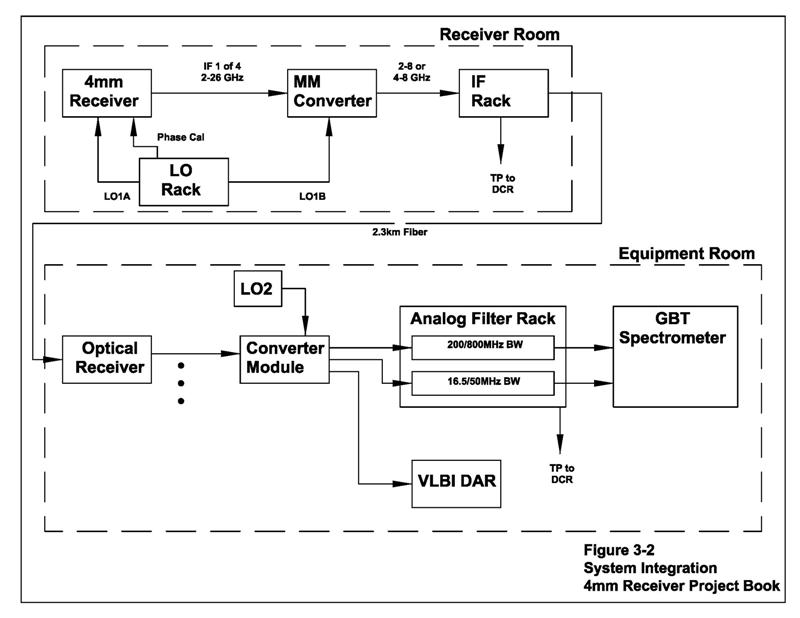
Figure 3-2: LO/IF System Integration (Click on image for higher resolution pdf)
3.2.1 LO Rack
The LO Rack contains two synthesizers and a LO Router switching network to provide 10MHz to 20GHz LO signals (LO1A and LO1B) to GBT receivers. LO1A will supply the 4mm receiver front-end at 66/4=16.5 GHz nominally. The LO Rack also contains a Phase Cal comb generator for VLBI observations which will be injected into the 4mm IF signals when required (the Phase Cal generator produces insufficient levels for injection at 68-92 GHz). LO1B will be used to supply a LO signal to the MM Converters.
3.2.1 MM Converter
The MM Converter is an existing four-channel subsystem on the receiver turret designed to interface between receivers with first IFs above 8 GHz and the fiber IF channels with frequency range 1-8 GHz. Currently it is used only with the 26-40 GHz (Ka) Receiver, but has additional input ports that will be used with the 4mm Receiver. Depending on the portion of the receiver output IF frequency range of 2-26 GHz being observed, the MM Converters will buffer and pass through 2-8 GHz, or down convert higher portions of the band to 4-8 GHz. The signals are then conveyed to the IF Rack and the fiber IF channels to the Jansky Lab. Because of fixed filters in the MM Converters and frequency constraints of the IF system, instantaneous bandwidth constraints of 4 or 6 GHz result.
3.2.2 IF Rack
The IF Rack on the receiver turret provides an IF router network, amplification, equalization, level set attenuators, filter selection, and then analog intensity modulates the IF signals onto optical fibers for transmission to the Jansky Lab GBT Equipment Room. The signal is also coupled off to square-law continuum detectors and then to the Digital Continuum Receiver (DCR) backend. Pointing observations are typically accomplished with these detectors and the DCR.
3.2.3 Equipment Room Distribution
In the GBT Equipment Room the IF signals carried by the optical fibers are demodulated in Optical Receiver modules. These modules include buffered power dividers producing four copies of each IF signal arriving from the telescope, so up to four Converter Modules can be connected to each front-end IF channel for observation of multiple spectral windows. The Converter Modules and LO2 synthesizers are used to tune to the proper input frequencies for the GBT Spectrometer or VLBI DAR systems.
3.3 Monitor and Control
The front-end incorporates temperature and vacuum sensors to monitor the cryogenic conditions. HFET bias current and voltages, power supply voltages, and other critical points are monitored. Basic monitor and control functions that do not have critical timing requirements are handled by a Standard Interface Board (SIB) on the Receiver Room Monitor/Control Bus (MCB) as is common in GBT receivers. The optical table and polarization selector mechanisms will also be controlled and monitored by the SIB. An YGOR manager (Rcvr68_92) serves as interface between the receiver hardware and the GBT M&C software system (see Ch. 7).
